Computer Communications Experiments
Marvin L. De Jong
Department of Mathematics-Physics
The School of the Ozarks
Pt. Lookout, MO
I. Introduction
This article describes a RS-232C interface circuit for serial input/output that can be used with any computer peripheral that uses such an interface. In this instance, the peripheral is a modem (NOVATION CAT) that can be used to transmit and receive data over telephone lines. Many modems require a RS-232C interface, hence the need for the circuit which in turn uses a 6551 ACIA (Asynchronous Communication Interface Adapter). The purpose of publishing this work is to find one or more persons who would be willing to experiment with computer communications over telephone lines. The article also describes some very simple software that can be used with a modem to transmit and receive messages over telephone lines. Later, more sophisticated load and dump routines can be written to transfer large amounts of data and/or programs from one user to another.
A true confession is that I am a beginner in the area of computer communications, and I would like to try some simple experiments before I fork-up a big subscription fee to one of the networks, only to find that my equipment or my understanding is inadequate. If you can obtain the necessary equipment and if you are in roughly the same position, write me a letter when you have said equipment operating and we will try to arrange a time to try our hardware and software on a telephone link. I might add that the software and hardware described here have not been tested, except in the "TEST" mode on my modem, in which case everything worked properly. I am aware that my routines are simple and slow, and I would welcome suggestions for improvement.
II. Circuits And Things
I sometimes wonder if there are any hardware enthusiasts like myself out there. You might let your editor/publisher know of your interests. My hardware fan club seems to be the null set, judging from the amount of mail I get. But here is another circuit even if no one ever builds it. You can always buy an RS-232C interface anyway. The circuit is shown in Figure 1. It consists of three integrated circuits, a 6551 ACIA, a MC1489 RS-232 line receiver, and a MC1483 RS-232 line driver. The latter two circuits change the RS-232 signal levels to TTL levels, and TTL level signals to RS-232 signal levels, respectively. The 6551 ACIA operates at TTL levels (5 volts is logic one, zero volts is logic zero), while the modem operates at RS-232C signal levels (see Michael E. Day's RS232 Communications in COMPUTE!, September/October 1980, page 26). The power connections for the MC1488 and 1489 devices are given in Table 1.
| Table 1. Power Connections for the RS-232 line driver and line receiver. | |||
| MC1488 | Pin 1 = -12V | Pin 14 = +12V | Pin 7 = GND |
| MC1489 | Pin 14 = +5V | Pin 7 = GND |
The connections to the left of the 6551 ACIA are made to the user's microcomputer system. Most of the signals are standard 6502 system bus signals, and require no explanation. Thus, address lines Aθ and A1 are used to address the four registers of the 6551, and are connected to the register-select pins RSθ and RS1. (You will probably want to obtain a specification sheet from either Rockwell or Synertek when you get your 6551; in fact, I advise you not to build the circuit without a spec sheet.) The data bus connections are shown in Figure 1, as well as several of the 6502 control lines (R/W, θ2,
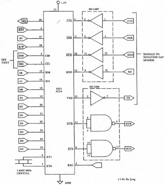
The chip select pins must be controlled by the address decoding circuitry in your microcomputer system, or else you must add your own address decoding circuitry to produce the chip select pulses. Since I have an AIM 65 system, I used one of the device selects available on the expansion connector, namely
We turn next to the signals on the right-hand side of the 6551 as it is shown in Figure 1. The RXC input to the 6551 is the easiest to explain because it is not used in this application. The remaining pins have labels that are almost identical to the RS-232C designations. In fact, the only one that is different is the
Although the signal designations on the 6551 ACIA are almost identical to the RS-232C labels, the signal levels are not, and some arrangement must be made to transform the TTL levels of the 6551 to the RS-232C signal levels. We chose to use integrated circuits designed expressly for that task, namely the 1488 and the 1489 line driver and line receiver. Note that the 1488 requires a positive and negative supply voltage as well as ground. Also, the RS-232C ground (pin 7 on the DB-225 connector) should have the same ground as the 1488 and the 1489. The connections in Figure 1 that are found on the right-hand side of the figure made up a rather complete RS-232C serial interface that may be used to interface to a variety of peripheral devices. Furthermore, the fact that the data format and Baud rate of the 6551 are under the programmer's control makes this an extremely flexible RS-232C interface.
Since computer communication by telephone is the subject of this article, a modem is required. There are a variety of modems with RS-232C interfaces on the market and we do not wish to make any recommendations about them. I purchased a Novation Cat because that appears to be one of the more popular devices. Skyles Electric Works and other advertisers in COMPUTE! offer modems for sale. In any case, my Novation Cat requires the signals designated in Figure 1 in addition to the signal ground. Other modems may require the DTR and RTS signals so we have shown the correct TTL-to-RS-232C interface in the event you may need these signals.
This completes our description of the circuit and we turn next to a simple program that is supposed to allow communication to take place using the 6551 ACIA.
III. A Simple Communications Program
A program that was designed to allow two people to communicate over telephone lines with their computers is given in Listing 1 and a flowchart is shown in Figure 2. This program is very simple and very slow, and it is offered here merely as a way to test the circuit, the program, and the modem. Eventually, one would want to construct more elaborate routines to transfer information quickly. Our interest here is in experimenting for the sake of learning. Hence there is no necessity for encryption devices, bells, whistles or even parity checks.
Here is how it is supposed to work. The caller loads the program and places his modem in the originate mode with full-duplex operation selected. He loads the indirect jump location with the vector $0F13 so that after the program is begun, his program will go to the transmit loop.
He makes the telephone call to an anxiously awaiting friend who also has this interface and this program operating. The friend has loaded the in�direct jump location at $0000 and $0001 with the vector $0F26 (remember, $26 goes in $0000 and $0F goes in $0001). The friend has also placed his modem in the answer mode with full-duplex operation selected. After an informal chat, both friends put their modems into action by placing the handset into the muffs (assuming acoustic modems). The originator begins to type a message.
He ends his part of the message with an ‘EOT’ character (Control D on your keyboard). While he is transmitting, the friend's program echoes the message back to the originator where it is read and printed by the computer. It's nice to see what you have said, and to know that it got where it was going with no mistakes. When an ‘EOT’ character is sent, it automatically transfers the originator's program to the receive loop and the receiver's program to the send loop, giving him a chance to retaliate. Having made no visible symbol to indicate when this changeover takes place, may I suggest sending a question mark, or perhaps there is some CB lingo that suggests it is the other person's turn to talk. If all else fails, pick up the handset and holler something. Do not change your modem from its original answer or originate mode.
| Listing 1. An Experimental Communications Routine. | |||
| $0F00 A9 0B | START | LDA #$0B | Initialize the 6551 by loading the command register (see 6551 spec sheet for details). |
| 0F02 8D 02 94 | STA CMNDRG | ||
| 0F05 A9 13 | LDA #$13 | Load the control register for 8-bit word length and Baud rate of 110. | |
| 0F07 8D 03 94 | STA CNTRG | ||
| 0F0A 78 | SEI | Prevent interrupts. | |
| 0F0B D8 | CLD | Clear decimal mode. | |
| 0F0C EA | NOP | A mistake of mine. | |
| 0F0D AD 01 94 | LDA STATUS | Clear any interrupts on the 6551. | |
| 0F10 6C 00 00 | JMP (THERE) | Jump to transmit loop to transmit, receive loop to receive. Get a character from the keyboard read routine. Send it to the 6551 transmit subroutine. If an "End of Transmission" (Control D) is sent, branch to receive loop. | |
| 0F13 20 3C E9 | TXLOOP | JSR KYBD | |
| 0F16 20 F0 0F | JSR TXMIT | ||
| 0F19 C9 04 | CMP #‘EOT’ | ||
| 0F1B F0 09 | BEQ RXLOOP | ||
| 0F1D 20 E0 0F | JSR RCVDAT | Get the echo from the receive subroutine. | |
| 0F20 20 7A E9 | JSR OUTPUT | Output it to your own printer to see what you sent. Force a jump back to TXLOOP and get another character to send. | |
| 0F23 18 | CLC | ||
| 0F24 90 ED | BCC TXLOOP | ||
| 0F26 20 E0 0F | RXLOOP | JSR RCVDAT | Wait for a character to be sent. |
| 0F29 C9 04 | CMP #‘EOT’ | Is he finished with his transmission? | |
| 0F2B F0 E6 | BEQ TXLOOP | Yes, then go to transmit loop. | |
| 0F2D 20 F0 0F | JSR TXMIT | Echo the character that was sent. | |
| 0F30 20 7A E9 | JSR OUTPUT | Output the character to your printer. | |
| 0F33 18 | CLC | Force a jump back to RXLOOP and get another character when it is sent. | |
| 0F34 90 F0 | BCC RXLOOP | ||
| Subroutines | |||
| 0FE0 AD 01 94 | RCVDAT | LDA STATUS | Read the status register to see if a word has been received, otherwise wait for one. |
| 0FE3 29 08 | AND #$08 | ||
| 0FE5 F0 F9 | BEQ RCVDAT | ||
| 0FE7 AD 00 94 | LDA RCVRG | Get the word from the receiver register. | |
| 0FEA 60 | RTS | Return to the calling program. | |
| 0FF0 48 | TXMIT | PHA | Save the accumulator temporarily |
| 0FF1 AD 01 94 | WAIT | LDA STATUS | Is the transmitter register empty? |
| 0FF4 29 10 | AND #$10 | No. Wait until it is. | |
| 0FF6 F0 F9 | BEQ WAIT | ||
| 0FF8 68 | PLA | Get the character from the stack. | |
| 0FF9 8D 00 94 | STA TMTRG | Store it in the 6551 transmit register. | |
| 0FFC 60 | RTS | Return to the calling program. |
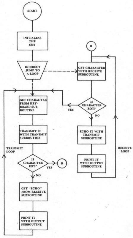
Figure 2. Flowchart of the Transmit/Receive Program. See text for details.
So back and forth the conversation goes. Once you have the transmit option in your hands nothing can stop you from talking until you send an 'EOT' and give your friend a chance to say something. Clearly, the program lacks a certain elegance (it may not even work, in which case it lacks a whole lot of elegance), but maybe it will get some fun started. By the way, the originator of the phone call usually gets the phone bill.
Study the flowchart and the program listing. The program begins by intitializing the 6551. An eight-bit word (TTY compatible) is used, with the parity check disabled, and one stop bit is sent. The Baud rate chosen here is 110, but it should be possible to go to 300 Baud. Both participants must have the same rate. Next, the program jumps to either the receive loop or the transmit loop depending on the vector loaded into $0000 and $0001. This was a crude way to start, but it should work.
In the transmit loop the program first waits for an input from a keyboard read routine. The address in the program belongs to an AIM 65 monitor subroutine that returns the ASCII representation of the depressed key in the accumulator. This character is sent by calling the transmit subroutine which loads the 6551 transmit register with the character. The 6551 takes over and sends the character. The program then waits for the character to be echoed from the other telephone and computer. The echoed character is printed to make sure that what was sent was actually received. Then control returns to the keyboard subroutine to wait for the next character to be sent.
In the receive loop the program jumps to the receive subroutine that watches the 6551 until a character is in the receive data register. If this character is an 'EOT' then control goes back to the transmit loop and you may begin transmitting. Otherwise the received character is immediately echoed back to the sender and also printed with your OUTPUT routine. Again, the address of the OUTPUT routine in Listing 1 belongs to an AIM 65 subroutine. Both the KYBD and OUTPUT subroutines must be supplied by the user's monitor or the user himself, otherwise the program in Listing 1 is complete.
While in the transmit loop, the selection of the 'EOT' character by the sender will automatically transfer control out of the transmit loop into the receive loop. Note again that no bells or whistles have been programmed to occur when you send an 'EOT' character, so if you are transmitting you better let your friend know you are passing control of the system to him.
So hopefully all this will work. If it doesn't you have only me to blame, and I will not assume the cost of your labor or your equipment to conduct this experiment. Perhaps it would be best if you waited until someone else tried it; think it over before you take the plunge.
Besides, my next project is to launch a 6502 Communications Satellite using dynamite in my back yard and you may want to save your money to buy shares in that enterprise.
References
1. De Jong, Marvin L., Programming & Interfacing the 6502, With Experiments, Howard W. Sams & Co., Inc. Indianapolis, 1980.
2. Day, Michael E., "RS232 Communications,", COMPUTE!, Sept/Oct 1980, 26.
3. Ciarcia, Steve, "I/O Expansion for the TRS-80," BYTE, June 1980, 42.