Maze Generator
Charles Bond
Sunnyvale, CA
Editor's Note: This program (versions here for PET Microsoft and Atari) can be the basis for many excellent games. When you come up with something interesting—send it in to COMPUTE!—RTM
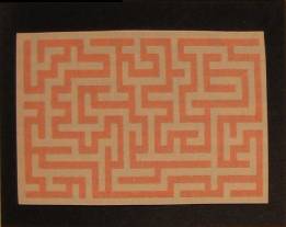
Here's a remarkably short algorithm which produces random mazes of any desired size directly on your CRT screen. The program will create mazes on any microcomputer which allows memory mapped graphics. Details are provided for directly applying it to the COMMODORE PET and the Atari 400/800 computers. A typical maze generated by the program is shown in Figure 2.
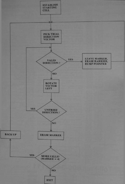
To understand how it works, refer to the flowchart in Figure 1 and the program listing. The following explanation should clarify the details.
The Background Field
The algorithm operates on a background field which must be generated on the screen prior to line number 200 in Program 1. The field must consist of an odd number of horizontal rows, each containing an odd number of cells: a rectangular array. It's convenient to think of the field as a two dimensional array with the upper left corner having coordinates ‘X’ = 0 and ‘Y’ = 0, where ‘X’ is the horizontal direction and ‘Y’ is vertical. No coordinates are used to identify absolute locations by the program, but the concept is useful in configuring the field.
Given that the upper left cell of the field has coordinates 0,0 then the terminal coordinates both horizontally and vertically must be even numbers. In addition, the background field must be surrounded on all sides by memory cells whose contents are different from the number used to identify the field. That is, if the field consists of reversed (or inverse video) spaces, then the number corresponding to that character must not be visually adjacent to the field.
This could happen inadvertently if the screen RAM and system ROM have contiguous addresses. A sufficient precaution is to avoid covering the entire screen with field. Leave at least one space at the beginning or end of each line and, in general, leave the uppermost and lowermost lines on the screen blank.
The Maze Generator
The creation of the maze begins by placing a special marker in a suitable starting square. The program here always begins at the square just inside the upper left cell of the previously drawn field. (Note that with our coordinate scheme this would be cell 1,1). Any cell with odd numbered coordinates would work, however, as long as it is internal to the field.
Next, a random direction is chosen by invoking the random number generator in your machine and producing an integer from 0 to 3. This integer, with the aid of a short table, determines a direction and a corresponding cell just two steps away from the current cell. This new cell is examined (PEEKed) to see if it is part of the field. If it is, the direction integer is put there as a marker and the barrier between it and the current cell is erased.
In addition, the pointer to the current cell is moved to point to the new one. This process is repeated until the new cell fails the test; i.e., it is not a field cell. When this happens, the direction vector is rotated 90 degrees and the test is repeated. Thus, the path carved out of the field will continue until a "dead-end" is reached.
A dead-end, incidentally, could occur in as few as five steps. When it does occur, we can make use of the markers which were dropped along the way "Hansel and Gretel" style. These can be checked to determine which direction we came from, so that we can back up and look for untrodden paths. So long as none can be found, the program will back up, one step at a time, erasing the markers as it goes. When a new direction can be taken, the pointer is set off in that direction, and the process continues as before.
Ultimately, the pointer will return to the start, a condition which is detected by the recovery of the special starting (now "ending") marker. This cell is then blanked and the program is done, leaving the pointer as it was at the start.
The Program
Program 1 contains the complete program as implemented on the PET computer, but it is applicable to other machines. The direction table set up in lines 100 and 110 converts an integer to an address offset. In this case (40 column screen), we wish to be able to step two cells to the right, up, left, or down. The memory addresses of these cells differ from that of the current one by 2, —80, —2, and 80, respectively. For computers with 64 column displays, the 80's should be replaced by 128's; for the Atari no change is needed.
Line 120 contains machine-dependent variables. ‘SC’ is the memory address of the start of screen RAM. For the Atari use the following:
120 WL = 128: HL = 0: SC = PEEK(88) + 256*PEEK(89): A = SC + 43: REM THESE VALUES FOR ATARI
Lines 130–160 establish the background field on the screen. For the PET we chose 23 rows of 39 cells each. The Atari, with default tab settings, will require a slightly smaller field. [See Program 3 — Ed.]
The rest of the program draws the maze, as previously explained. Line 310 is simply a convenient stopping point which prevents the screen from scrolling.
It may not be immediately obvious that this algorithm always produces a maze with only one non-trivial path between any two points, or that the maze will always be completely filled, but this can be proved. While the proofs will not be provided here, math buffs may find it interesting that for a maze of any size there will be exactly:
(H-1)(v-1)/2 - 1 empty cells in the completed maze,
where H is the number of cells in each field row and V is the number of rows.
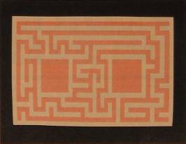
An interesting feature of this algorithm is that it works equally well in certain types of non-rectangular fields. U-shaped fields or fields with holes in them are quite suitable—as long as certain restrictions are observed. Just make sure that the coordinates of the upper left and lower right cells of any cut out area are pairs of odd numbers. Also, if there is a single row of field cells between any cut out areas and the outside of the original field, it may be removed. See Figure 3.
The Mouse
With slight modifications the Maze Generator can become an artificial "mouse." Programs 2 and 4 show a routine which can be appended to the Maze Generator and which create a mouse which roams the maze endlessly. The mouse adheres to a "left-hand rule" when a choice of directions is possible. That is, when it is confronted with a branch-point it will move off to the left, if possible. Otherwise it' will go forward. When no choice is available it will turn around.
Figure 1. Maze Generator Flow Chart