A Simple Printer Interface For The Apple II
Marvin L DeJong
Dept. of Math-Physics
The School of the Ozarks
Pt. Lookout, MO
In the January 1981 issue (COMPUTE! #8) I described a simple circuit that could be used with an Apple II to perform the experiments in my book(1). The circuit provided one eight-bit output port. These two ports can also be used to interface the Apple II to a parallel port printer.
The Circuit
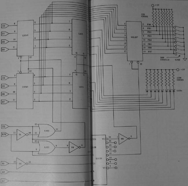
For the unfortunates who do not have a copy of COMPUTE! #8, I have included the circuit diagram of the peripheral I/O card in this article. It is shown in Figure 1. My circuit was wire wrapped on a Vector Electronic #4609 plugboard which fits into the peripheral card connectors on the Apple II. For the purpose of this application, the eight LEDs and the DIP switch (with pull-up resistors) are not needed. They are only used if you wish to use the peripheral I/O board in conjunction with the experiments in my book. You may also wish to experiment with the possibility of omitting the 74LS242 bus transceivers and the associated logic, simplifying the circuit further. This would leave only the 74LS138, an inverter, the two 74LS75s, and the 81LS97. Since only one bit of the input port is used to interface to the printer, you may wish to replace the 81LS97 with a 74LS125. I used the circuit as it is shown in Figure 1, with the DIP switch removed from the socket.
My printer (which was not the one used to make the listings in this article) is a MICROTEK MT-80P which I normally use to interface to one of my TRS-80 machines. It claims to have a "Centronics-compatible interface," so perhaps the circuit and software we describe here may also be used with Centronics printers. The printer has eight data lines and several handshaking lines. The eighth bit is not used by the printer: it uses seven-bit ASCII. So seven bits of the output port on our peripheral I/O card are used to send the character to be printed to the MT-80P printer.
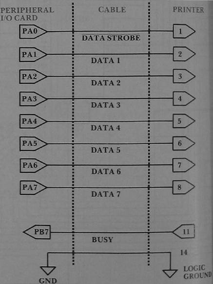
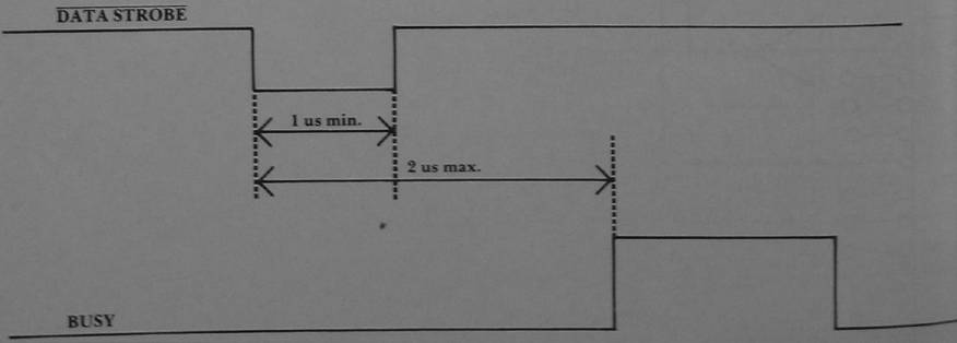
Two handshaking lines are used, DATA STROBE and BUSY. The microcomputer must supply a logic-zero pulse (strobe) of at least one microsecond in duration when the character on the data lines is to be read by the printer. Thus, the DATA STROBE line is controlled by the Apple II peripheral I/O card. In particular, I used bit zero (PA0 in Figure 1) to control the DATA STROBE line, while the seven-bit ASCII character appears on bits one to seven (PA1 – PA7). When the DATA STROBE pulse is sent, the printer responds by bringing the BUSY line to logic one. It stays at logic one until the character is read. This will only take about 40 microseconds unless the buffer is full. The BUSY line will stay high until there is room in the buffer. Thus, the BUSY line is connected to bit seven of the input port on the peripheral I/O card where it may be watched with a BMI instruction. Figure 2 shows the connections to the printer, and Figure 3 illustrates the handshaking sequence.
The Software
The machine language software driver routine is shown in Program 1. It is used with DOS 3.3, but other versions should work equally well. The machine language program consists of two parts. The first part starts with line six in the listing and ends with line 19 (locations $02C0 — $02DB). It has two functions:
- It sets up the Apple II output registers ($36 — $37) to point to the printer routine at $02E0, and it jumps to a DOS routine to fix the DOS output register. (See pages 103–104 in the APPLE II DOS MANUAL.)
- It loads a form-feed character, $0C, into the printer and pulses the DATA STROBE line.
The second part of the machine language routine is the actual print routine. It puts an ASCII character on the data lines to the printer and then it pulses the DATA STROBE line, but it does not do this unless the BUSY line is at logic zero, indicating that the printer is not busy. Finally, it jumps the monitor COUT routine that prints the character on the video monitor screen, before returning to the DOS program.
In Program 2 I show a greeting program that is the INITilization program on the slave diskette for our DOS 3.3. It gives the user the chance to call PRINTS, the object code file that is also stored on the slave diskette. This completes the description of the software for this system. Refer to the comments for more details regarding the software.
If you are not running a disk system, then to operate the printer load the machine language programs in Program 1 with a single modification. Replace the JMP DOSSYS instruction with a BRK. Execute the program from the monitor, starting at $02C0. You can then either stay in the monitor or return to BASIC with a control B.
Notice that the software is located in page two of memory. If you type in a very long sentence you may wipe out your program, since it is part of the input buffer for the Apple II. Ideally, you would PROM the software. (We should add that the software as shown assumes that the peripheral I/O card is in slot one on the Apple II. The software, assuming the peripheral I/O card is in slot one, would be loaded into locations $C100 upward, starting with the instructions at $02E0 in Program 1.
To initialize the printer you would still want to execute instructions from $02C8 through $02D8, with a BRK replacing the JMP DOSSYS at location $02D9. Thereafter a PR#1 command would produce an active printer, and a PR#0 would disable it. I should add that I have not tried to run the system with the program in EPROM, but I think that I understand my Apple II enough to make the instructions just given. I would very much like to hear from someone who might try this approach.
Obviously this interface circuit will work with almost any microcomputer system and any parallel printer. Even the software requires little modification to work with any 6502 based system. The card to mount the components is the most expensive item, $23.25. Note that the card I used has another edge connector not used to plug into the Apple II, and I used that connector to attach to our printer cable. It accepts a standard 20/40 edge connector, but my printer used a 19/36 edge connector, so I sawed and filed to fit. It has a big price advantage over the usual parallel interfaces found in your catalogs.
Reference
1M.L. De Jong, PROGRAMMING & INTERFACING THE 6502, WITH EXPERIMENTS, Howard W. Sams & Co., Inc. 4300 West 62nd St., Indianapolis, Indiana 46268, 1980. $15.95
Program 1.
SOURCE FILE: PRINTS
0036:            1 APREGLO EQU	$0036
0037:            2 APREGHI EQU	$0037
C090:            3 OUTPORT EQU	$C090
C094:            4 INPORT  EQU	$C094
03EA:            5 DOSSYS  EQU	$03EA
----- NEXT OBJECT FILE NAME IS PRINTS.OBJ0
02CO:            6         ORG  $02C0
02C0:A9 EO       7 INITIAL LDA  #$E0       ;SET UP APPLE OUTPUT REGISTERS
02C2:85 36       8         STA  APREGLO    ;TO POINT TO PRINTER ROUTINE
02C4:A9 02       9         LDA  #$02
02C6:85 37      10         STA  APREGHI
02C8:A9 0C      11         LDA  #$0C       ;SEND FORM FEED TO PRINTER
02CA:38         12         SEC
02CB:2A         13         ROL  A          PUT CHARACTER IN HIGH ORDER 7 BITS
02CC:8D 90 CO   14         STA  OUTPORT    ;OUTPUT THE CHARACTER WITH BIT ZEROAT
 LOGIC ONE
02CF:29 FE      15         AND  #$FE       ;NEXT BRING BIT ZERO TO LOGIC ZERO TO
SEND DATA PULSE
02D1:8D 90 CO   16         STA  OUTPORT
02D4:09 01      17         ORA  #$01       ;BRING BIT ZERO TO LOGIC ONE AGAIN
02D6:8D 90 CO   18         STA  OUTPORT
02D9:4C EA 03   19         JMP  DOSSYS     ;JUMP TO DISK ROUTINE TO EXCHANGE OUTP
UT REGISTERS
02DC:EA         20         NOP
02DD:EA         21         NOP
02DE:EA         22         NOP
02DF:EA         23         NOP
02E0:48         24         PHA              ;SAVE CHARACTER
02E1:AD 94 CO   25 BUSY    LDA  INPORT     IS PRINTER STILL BUSY?
02E4:30 FB      26         BMI  BUSY       ;YES, THEN DONT BOTHER IT
02E6:68         27         PLA              GET CHARACTER BACK
02E7:48         28         PHA              AND SAVE IT AGAIN
02E8:38         29         SEC              SET CARRY TO ROTATE A ONE INTO BIT ZE
RO
02E9:2A         30         ROL  A          MOVE CHARACTER UP ONE BIT
02EA:8D 90 CO   31         STA  OUTPORT    OUTPUT IT