A Simple 2716 EPROM Programmer For The PET
Phil Gentile
Belton, MO
PET owners who are involved in machine language programming usually collect a number of subroutines that aid in the operation of the PET. These subroutines may consist of repeat key functions, screen print programs, or other helpful machine language routines which may be written by the user or found in magazines.
These subroutines must all be loaded into RAM before they can be used. The second cassette buffer, or a portion of high RAM, is usually the choice.
Now, for just a few dollars and a little time, you may put all of these programs in EPROM [Erasable, Programmable ROM. These chips are a compromise between RAM and ROM – like ROM they will hold information with the power off. Like RAM, you can reprogram them (by erasing them using special techniques).] EPROM is a better location for these programs for two reasons. First, if the programs are in EPROM, they don't have to be loaded; the programs are there when you power up. Second, in EPROM, the programs don't take up any of your precious RAM space.
There are a number of EPROM programmers on the market, ranging in price from many hundreds down to fifty or sixty dollars. They all do basically the same thing, the expensive ones are just fancier and more versatile in the types of EPROMs which they can program.
This EPROM programmer, as it is presented here, can only program a 2716, or 2716 compatible EPROM. The 2716 is a 2K byte EPROM. I have found 2K to be more than enough space to hold all of the machine language programs that I need, including the DOS Wedge. If you find that you need more space, the programmer and the accompanying software may be easily modified to program larger EPROMs. You may do this by connecting the unused address lines on IC-2, and modifying the M/L "program pulse" subroutine to satisfy the requirements of the EPROM you select.
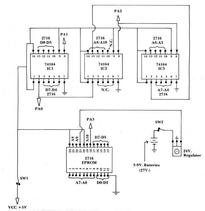
The EPROM programmer is very simple. It consists of three 74164, eight bit shift registers, one 24 volt regulator, a couple of switches and three 9 volt batteries. One shift register holds the data shifted out by the PET. The remaining two shift registers hold the EPROM addresses as they are shifted out. The 24 volt regulator reduces the voltage from the series wired batteries down to the 24 volts necessary to program the 2716 EPROM. The PET, using the accompanying software and the PET's user port, supplies all of the necessary data, addresses, and signals to program the EPROM. The five volt VCC supply can also be taken from the PET if you use low power (Is) type IC's. This circuit, using "Is" IC's, will draw approximately 100 Ma. This small amount of current may safely be drawn from pin B of the second cassette edge connector (J3).
You may use any type of construction you wish to build the circuit. Wire wound, PC board, or plug-in type breadboard are all OK. If you wish to save the considerable expense of a zero force socket for the EPROM (about $9.00), then I would recommend the plug-in type breadboard construction. The EPROM can be easily inserted and removed from this type of board, reducing the chance of damage to the EPROM pins.
The 74164 shift registers are common IC's and can be purchased in most electronics supply stores. The 24 volt regulator is also a common component. Be sure to get the positive rather than the negative type regulator. The switches are miniature SPDT. The batteries used are standard 9 volt transistor type. I used the heavy-duty versions.
There are only a few things to watch out for. Be sure that the regulator is wired properly. The allowable voltage range on pin 21 of the 2716 EPROM is 24 to 26 volts. Be careful when handling the EPROM. Static electricity on the pins may destroy it. Last, but most important, always follow the proper sequence when applying the voltages to the EPROM. The 5 volt VCC supply must be turned on first, followed by the 24 volt VPP supply. When turning the voltages off you must reverse this procedure. If you follow the instructions as they are given by the program, you will have no problem. If you don't, you may destroy your EPROM.
Software Control
The software to control the EPROM programmer consists of a small BASIC program and three small machine language subroutine modules that reside in RAM at 4100 through 4276.
The BASIC program is used primarily to interface with the user. It issues instructions for the operation of the EPROM programmer and accepts user information on where the machine language code (to be programmed into the EPROM) is located in the PET's memory. It also asks the user for the EPROM starting address. The BASIC program then gets the selected code from the PET's memory and passes it to the machine language modules. They, in turn, send the code to the EPROM programmer.
The first M/L module, located at 4104, sends the data from the PET's memory serially out over the PA-0 line. As it sends this data out over PA-0, it also sends a shift (clock) pulse out on the PA-1 line which is connected to the data register, IC-1. This clock pulse loads the data on PA-0 into the data register.
Next, the BASIC program jumps to the M/L routine, located at 4184, which shifts out the EPROM address. This routine sends the address out on the PA-0 line also, but it sends the shift signal out over the PA-2 line which is only connected to the address register (IC-2 & IC-3). Since the data register is not connected to the PA-2 line, the information stored in this register is not affected when the EPROM address information is shifted into the address register.
Finally, after all of the data and EPROM address information is safely stored in the registers, the machine language module located at 4107 sends a 50 milisecond "program" pulse to the 2716 EPROM telling it to store the byte of data in the selected EPROM address. This "program" signal is sent out over the PA-3 line. The BASIC program then begins the cycle all over again for the data contained in the next core location. This continues until all of the PET memory addresses, requested by the user, have been programmed into the EPROM. The BASIC and machine language programs occupy RAM locations 1025 through 4276. You may place your EPROM code anywhere else in RAM that you wish.
To use this EPROM programmer you must first, of course, have some machine language code that you want to put in EPROM. The example I will use here is a procedure for putting Commodore's DOS Wedge in EPROM. The machine language code for the DOS Wedge is completely relocatable. After the Wedge has been loaded from disk and executed, the Wedge M/L code resides in the PET's top 359 bytes of RAM. To find out exactly where this code has been stored, go to the machine language monitor and display locations $0070 thru $0072. The program that loads the Wedge, stuffs a jump to the address of the Wedge into these locations. If the Wedge has been loaded, you should see a "4C" in location $0070, followed by the low-byte, hi-byte address of the Wedge. On my 16K PET, this code reads, "4C 99 3E". This translates into the decimal location, 16025.
Now we know where the code for the DOS Wedge is in core, so let's put it into EPROM. First hook the EPROM programmer up to the PET's user port. Do not put the EPROM in its socket yet. Now hook up both the 5 volt and the 24 volt power supplies. Make sure that both of the switches on the programmer are turned off. Put the EPROM into it's socket on the programmer and load the EPROM programming software. The program will tell you to first turn on the 5 volt, and then the 24 volt power supplies. Do this in the sequence described.
The program will next ask you for the starting RAM address of the machine language code that you wish to put into the EPROM. In this case, this is the address that we found in locations $0071 and $0072. The low order byte of the address is in $0071, the high order byte in $0072. Convert this address to its decimal value, in the case of a 16K PET, 16025, and enter it. The next address that the program asks for is the ending address of the code. The DOS Wedge is 359 bytes long, so your ending address is 16383 and press return. Next, the program asks where you want the code to start in the EPROM. If you are using a new EPROM, without any code previously programmed into it, you will probably want to start in location zero. Enter the EPROM starting address and press RETURN. The machine language code for the DOS Wedge is now being programmed into your EPROM.
After it has finished programming the EPROM (approx. 1.5 minutes), the program will give you the last EPROM address programmed. If you started at EPROM address zero, this address will be 358. Write this address somewhere for future reference. Turn the power switches off in the order given by the program. Leave the EPROM in the socket for now.
Now that we have the Wedge in EPROM, we must tell the PET where we are going to put it. We'll use the same method that the Wedge loader uses. For the sake of this demonstration, we will assume that the EPROM is going to be placed in the PET's empty EPROM slot at address $9000. Go to the machine language monitor and display locations $03E4 through $03F0. Enter the following code starting in $03EF, "A9 4C 85 70 A9 00 85 71 A9 90 85 72 60." This code, when executed, will load a jump to location $9000 into locations $0070 thru 0072. Get out of the Monitor and execute the EPROM programmer program again. This time your starting RAM address will be the starting address of our little loader patch, 996 (hex 03E4). The ending RAM address will be 1008 (hex 03F0). The EPROM starting address will be one more than the EPROM ending address that we saved after our last run (358 + 1 = 359). When the program finishes, the EPROM contains everything we need to run the DOS Wedge from EPROM.
Turn the PET off and install the programmed EPROM in the EPROM socket at $9000. Turn the PET back on and jump to the EPROM starting address of our little loader program, SYS(37223), ($9000 = 36864 + 359 = 37223). You should now be able to execute any DOS Wedge command from the EPROM.
I don't know how long the 9 volt batteries will last. I have programmed a couple of EPROMs, and have done a lot of testing using the original set, they still seem to have a lot left.
With the software written partly in BASIC and partly in machine language this system will program approximately three bytes per second. If you wish to make it operate faster, the software could be written entirely in machine language.
If you are careful to follow the schematic, and in entering the program code, you will have an EPROM programmer costing around fifteen or twenty dollars. That is a lot cheaper than buying one. In addition, there is a lot more fun, satisfaction, and knowledge to be gained by building your own.
170 ** LOAD ML PROGRAM MODULES ***
180 POKE 53, 16 : POKE 4102, 0 : POKE 4103, 0
190 READ X, Y
200 F0R I = X TO Y
210 READ Z
220 POKE I, Z
230 NEXT I
240 :
250 POKE 59459, 15 : POKE 59471, 0
260 PRINT"{03 D0WN}TURN ON THE 5 VOLT POWER SUPPLY.
270 PRINT"AND PRESS RETURN.
280 PRINT
290 GETA$ : IFA$ = "" THEN 290
300 PRINT"NOW TURN ON THE 24 VOLT POWER SUPPLY
310 PRINT"AND PRESS RETURN.
320 PRINT
330 GETA$ : IFA$ = ""THEN 330
340 INPUT"STARTING RAM ADDRESS (DEC.)"; R1ST
350 INPUT"ENDING RAM ADDRESS (DEC.)"; R2E
360 PRINT : INPUT"STARTING EPROM ADDRESS (DEC.)";R3ST
370 IFR3 > 2047 THEN PRINT : PRINTR3" EXCEEDS 2716 EPROM SIZE." : PRINT : GOTO 360
380 N = R3 : GOSUB740
390 HI$ = LEFT$(N$, 2) : LO$ = RIGHT$(N$, 2)
400 N$ = "00" + HI$ : GOSUB 910 : POKE4102, N
410 N$ = "00" + LO$ : GOSUB 910 : POKE4103, N
420 :
430 REM *** SHIFT THE DATA OUT ***
440 :
450 PRINT"{CLEAR}PROGRAMMING FROM RAM LOCATION: " : PRINT
460 FOR K = R1 TO R2
470 PRINT K
480 A = PEEK (K)
490 POKE 4104, A
500 SYS (4152)
510 :
520 REM *** SHIFT ADDRESS OUT
530 :
540 SYS (4184)
550 :
560 REM *** SEND OUT THE M/L PROGRAM PULSE ~ ***
570 :
580 SYS (4107)
590 :
600 NEXT K
610 PRINT
620 HI = PEEK (4102)
630 LO = PEEK (4103)
640 N = HI : GOSUB 740 : HI$ = RIGHT$(N$, 2)
650 N = LO : GOSUB 740 : LO$ = RIGHT$(N$, 2)
660 N$ = HI$ + LO$ : GOSUB 910
670 PRINT "LAST EPROM ADDRESS WAS " N - 1
680 PRINT : PRINT "TURN OFF THE 24 VOLT SUPPLY
690 PRINT"AND THE 5 VOLT SUPPLY, IN THAT ORDER!"
700 PRINT"
710 END
720 :
730 REM ** DECIMAL TO HEX **
740 A = N : X = 0
750 A = A - 4096
760 IF A<0 THEN A = A + 4096 : Z = X : GOSUB 970 : E$ = X$ : GOTO 780
770 X = X + 1 : GOTO 750
780 B = A : X = 0
790 B = B - 256
800 IF B<0 THEN B = B + 256 : Z = X : GOSUB 970 : F$ = X$ : GOTO 820
810 X = X + 1 : GOTO 790
820 C = B : X = 0
830 C = C - 16
840 IF C<0 THEN C = C + 16 : Z = X : GOSUB 970 : G$ = X$ : GOTO 860
850 X = X + 1 : GOTO 830
860 D = C : Z = D : GOSUB 970 : H$ = X$
870 N$ = E$ + F$ + G$ + H$
880 RETURN
890 :
900 REM ** HEX TO DECIMAL **
910 X$ = RIGHT$(N$, 1) : GOSUB 1000 : D = Z
920 X$ = MID$(N$, 3, 1) : GOSUB 1000 : C = Z * 16
930 X$ = MID$ (N$, 2, 1) : GOSUB 1000 : B = Z * 256
940 X$ = LEFT$ (N$, 1) : GOSUB 1000 : A = Z * 4096
950 N = A + B + C + D
960 RETURN
970 IF Z<10 THEN X$ = STR$(Z) : X$ = RIGHT$(X$, 1) : RETURN
980 X$ = CHR$(Z + 55) : RETURN
990 :
1000 IF X$<"A" THEN Z = VAL(X$) : RETURN
1010 IF X$ = " " THEN Z = 0 : RETURN
1020 Z = (ASC (X$) - 55) : RETURN
1030 :
1040 REM *** DATA STATEMENTS FOR M/L CODE **
1050 DATA 4100, 4276
1060 DATA 169, 5, 141, 248, 3, 32, 169, 169, 5, 141, 9, 16, 32, 29, 16, 173
1070 DATA 9, 16, 201, 0, 240, 2, 208, 244, 96, 169, 8, 160, 144, 141, 79, 232
1080 DATA 162, 48, 202, 208, 253, 136, 208, 248, 169, 0, 141, 79, 232, 206, 9, 16
1090 DATA 96, 1, 2, 4, 162, 8, 173, 8, 16, 45, 53, 16, 141, 79, 232, 131100 DATA 54, 16, 141, 79, 232, 169, 0, 141, 79, 232, 202, 240, 6, 78, 8, 16
1110 DATA 76, 58, 16, 96, 173, 6, 16, 141, 4, 16, 173, 7, 16, 141, 5, 16
1120 DATA 162, 8, 173, 7, 16, 45, 53, 16, 141, 79, 232, 13, 55, 16, 141, 79
1130 DATA 232, 169, 0, 141, 79, 232, 202, 240, 6, 78, 7, 16, 76, 102, 16, 162
1140 DATA 8, 173, 6, 16, 45, 53, 16, 141, 79, 232, 13, 55, 16, 141, 79, 232
1150 DATA 169, 0, 141, 79, 232, 202, 240, 6, 78, 6, 16, 76, 133, 16, 24, 216
1160 DATA 173, 5, 16, 105, 1, 141, 7, 16, 173, 4, 16, 105, 0, 141, 6, 16
1170 DATA 96