FIGHTER ACES-Add A Second VIC Joystick
John Parr
This game, Fighter Aces, is fun in its own right. But it also shows a simple way to add a second joystick to your VIC for two-player games.
I spend many hours behind the CRT on my VIC, attempting one program or another, but when the work is done, I am not ashamed to play a game or two for relaxation. Many of the games that I like, however, require two joysticks.
Other programmers have circumvented this problem through the use of keys, but I find the use of keys awkward. Besides, most games use the same keys over and over, which I am sure must be wearing on my precious investment. The only answer to my dilemma, therefore, was to find some way of connecting a second joystick.
Before I went to work, I decided that I'd better find out a little bit about how the joysticks worked. As it turns out, the VIC joystick is just a lever connected to four micro switches at its base. When the stick is pressed in one direction, the lever closes the appropriate switch, grounding one of the pins on the games port. For diagonals, two switches are closed simultaneously, grounding two pins in the games port. When a pin is grounded, one bit is turned off in either memory location 37137 or in location 37152. (For any who do not know what a "bit" is, I refer you to COMPUTE!, November and December 1981, #'s 18 and 19, "An Introduction to Binary Numbers.")
From this understanding, I decided that the best place to hook a second joystick on was through the parallel user port. (As it turns out, PET users have been doing this for years.) After a little checking of my memory map, I decided to connect my second joystick on pins D through J, grounding to pin A. These pins are easily read through memory location 37136.
My next chore was to determine the most logical order in which to make my connections. I finally decided on a system by which any formulas for the first joystick could be used by the second. The following hookup is the result of my research.
Looking at the plug on the joystick, you will see this (minus the numbers, of course):
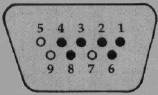
The filled-in holes represent pins which are used. You will notice that this is a mirror image to the diagram which is in your VIC book.
The following chart tells what each pin does:
Table.
| Pin number | Description |
| 1 | Up -Joy 0 |
| 2 | Down - Joy 1 |
| 3 | Left -Joy 2 |
| 4 | Right -Joy 3 |
| 6 | Fire Button |
| 8 | Ground |
Simply connect these pins to a 24-pin edge connector as follows:
| Joystick | Edge Connector | |
| 1 | to | E |
| 2 | to | F |
| 3 | to | H |
| 4 | to | D |
| 6 | to | J |
| 8 | to | A |
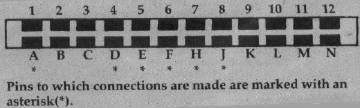
The 24-pin edge connector then plugs into the User I/O Port on the back of the VIC, which has the configuration shown in Figure 2.
These connections can be made either by replacing the existing joystick plug with the edge connector or by using a "patch" cord. A "patch" cord is an extension cord with one type of plug on one end (such as our edge connector and with a different type of plug on the other end (such as a connector like the one which is mounted on the side of your computer for the games port). I personally prefer the "patch" cord method, because then the joysticks can be interchanged if one wears more than the other. Also, if a joystick breaks for some reason, there need be no changes made to the replacement.
From the arrangement I have chosen, all formulas used on one joystick can be used on the other with little modification. Personally, I find the new joystick easier to use because all switches can be read from the same memory location with one simple PEEK. I like it so much, in fact, that it has become my main joystick.
Fighter Aces
Now that I have shown you how to connect this joystick, I will show you how to use it with one of my favorite games, Fighter Aces. In this game, two players engage in a "dog-fight" across your VIC's screen. The game ends at fifteen points; may the best pilot win!
As it is written, this program will run on any memory configuration the VIC can attain.
Before continuing, I must explain the use of the decimal points. The decimal point is a constant for the number zero. The only difference between the use of the decimal point and the use of a zero is that decimal points will speed program execution. If you feel ambitious, try replacing the decimals with zeros to see what I mean.
At last, we have arrived at our program description. The code follows a fairly simple algorithm, so with the explanation, you should be able to understand its workings.
| Lines | Description |
| 10-50 | Set the program to run with any memory by changing the locations of the screen and color. Also, these lines move the variable storage above the user-defined characters if your computer is expanded by 8K or more; if not, the program sets the end of memory below the special characters, thus protecting them for any memory configuration. |
| 60-150 | Set up the variables and the screen before the game begins. |
| 160-170 | Get values for each joystick. |
| 180-220 | Check for a fire button; see if a shot has already been fired. Each shot is checked here to see if it has gone to the end of its limited range. Note: By eliminating line 180 and the NEXT on line 290, the biplanes will be more responsive, but the shots will be slower. Conversely, if the value of the loop is upped, the shots will move faster, but the planes will be harder to control. |
| 230-280 | Move the shots checking for out of bounds, out of range, and a hit. |
| 290-340 | Set new direction on each biplane and determine which type of biplane is to be POKEd. |
| 350-400 | Move each biplane, checking for out of bounds and crashes. |
| 410-440 | Subroutine to determine what a shot hit. (Control tower, another shot, or a biplane.) |
| 450-540 | Subroutine for an explosion. Also checks fora mid air collision and updates the score. If either score equals fifteen, the ending flag(s) are set. |
| 550-650 | Game over routine. |
| 660-790 | Create the biplanes and print the title page. |
Important Variables:
| S | The first sound channel. |
| V% | The starting address of the video display. |
| C | The difference between the screen and color locations. |
| P%() | Position of each plane on the screen. |
| SP%() | Position on the screen of each shot. |
| SD%() | Direction of each shot. |
| SF%() | Flag to show whether a shot is on the screen and, if it is, how far it has to travel. |
| D%() | Direction of each plane. |
| A%() | The attitude of each plane. |
| SC%() | The score for each player. |
| E%() | Flag to show if someone has fifteen points. |
| G%() | The number of games that each player has won. |
| M%() | Value from each joystick. |
| L% | Flag for the biplane being out of screen limits. |