Part IV
Commodore 64 Video - A Guided Tour
Jim Butterfield, Associate Editor
In Part 4 of this guided tour of the impressive video capabilities of the Commodore 64, we take a look at the video structure itself and explore program design considerations.
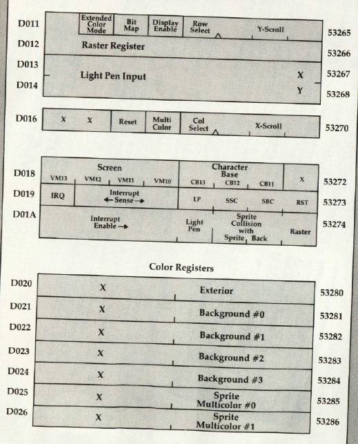
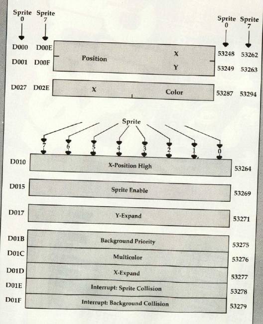
The story so far: we're touring the 6566 chip, which gives the Commodore 64 its video. We have noted that the chip goes to memory for its video information, but can only reach 16K; the computer controls which 16K bank via control lines in 56576 (hex DD00). Then we looked through the functions of the video control words - sprite and non-sprite - at 53248 to 53286 (hex D000 to D026).
We've examined all the bits in the video chip control registers. Now let's ease back and look at the 64's video structure. We'll talk a bit about program design considerations.
A Single 16K Slice
In Part 1 of this series (February 1983), we discussed how the video chip gets its screen information directly from memory. We indicated that the chip must dig out all of its information from a single 16K slice. We might draw this as a diagram (see the figure).
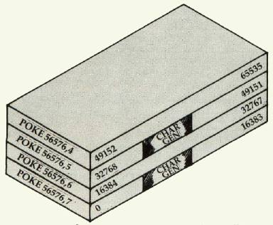
We can control which slice we want by manipulating the two low bits in address 56576 (hex DD00). Normally, the processor picks the slice from 0 to 16383.
Once we've picked a 16K block, we must get all screen data from this block: the "screen memory," the character set, and the sprites. We cannot get the screen data from one block, the character base from another, and sprites from still another. Because we are restricted, we must do a little planning, and design our video information into our program.
After we have picked the 16K slice, we must set the video matrix (screen memory) to some point within it. We may pick any multiple of 1024 as a starting address. The normal 64 configuration is set to a value of one, meaning we take the screen information from memory starting at address 1024. The video matrix, you may remember, is stored in the high nybble (that means multiply it by 16) of 53272 (hex D018).
We must pick our character base next. If we're in normal resolution, we may pick any even multiple of 1024 as a starting address: i.e., 0, 2048, 4096, etc. If we're in high resolution mode, we must pick only values of zero and eight, meaning that the hi-res starting address will be either 0 or 8192. The normal 64 configuration is set to four or six for either graphics or text mode, meaning we take our character set from 4096 or 6144. You probably remember that the character base is stored in the low nybble of 53272.
So we'd expect a normal 64 to place into address 53272: a video matrix of one, times 16, plus a character base of four or six, yielding a total of 20 or 22. You may in fact see 21 or 23 if you PEEK the location, but the extra bit doesn't matter - it's not used. And if we switch to high resolution without changing anything else, our character base of four or six will be trimmed back to zero - explaining why we saw zero page when we tried POKE 53265,48 in Part 1 of this series.
Let's try a few specific design jobs.
Task 1: Simple Graphics
We're quite satisfied with the screen and character set, but we'd like to add a few sprites to liven things up. Fine, the normal 64 configuration leaves room for about four sprite drawings (numbers 11, 13, 14, and 15), provided we don't need to use cassette tape during the program run. This may be enough for a lot of animation; all eight sprites could use a single drawing, if that suited the task.
If we needed more than four drawings, we might be tempted to move the start-of-BASIC pointer to a higher location, making room for the extras. That can work quite well, but it will probably call for two programs: a configuring program and a final program. It's hard for a program to reconfigure itself and survive.
Task 2: New Character Sets
If we wish to use the regular character set as well as new characters that we might devise, we'll want to stay in the memory blocks from 0 to 16383 or 32768 to 49151. These two blocks contain the ROM character generator at offset 4096 to 8191. If we don't need regular characters at all (if we intend to use our own) it may be more convenient to switch to either of the other two blocks: 16384 to 32767 or 49152 to 65535. Since there's nothing but RAM in these two, we may find more room.
Note that some of these RAM addresses are "hidden" beneath ROMs–BASIC from 40960 to 49151, and the Kernal from 57344 to 65535. The video chip sees only the RAM; but in a normally configured 64 system, programs will see only the ROM. You can POKE or store to the RAM beneath, but when you PEEK or load from these addresses, you'll get the ROM. That's OK; the video chip sees the RAM locations you have POKEd. Result: something for nothing! You can build a character base into RAM, and not lose any memory from your system.
Task 3: Emulating A PET
This is a clear-cut task. We want to move the screen to the same place that the PET uses the screen. That's very straightforward from a video chip standpoint. (Note: If you type the following POKEs in one at a time, you may have to type blind for some of them.) The PET screen belongs at 32768, so we must select that slice with:
POKE 56576,5
so that we'll pick up RAM starting at 32768. The ROM character generator is still in place.
Since we want the screen (video matrix) to be positioned right at the start of the block, we must set it to a value of zero. The character base can stay at its value of four (for graphics mode), so we must set up address 53272 with zero times 16 plus four:
POKE 53272,4
That completes the video, but we have a few other things to do to make BASIC work in a sound manner. We must tell BASIC where the new screen is located:
POKE 648,128
And finally, we should set the start and end of BASIC to correspond with a 32K PET:
POKE 1024,0:POKE 44,4:POKE 56,128:NEW
Clear the screen, and the job's done. Zero page usage is still different, so not all PEEKs and POKEs will automatically work on this reconfigured system; but BASIC and screen now match the PET.
Task 4: High Resolution Plotting
There are only eight places in memory that we can place a high resolution screen: 0, 8192, 16384, 24576, 32768, 40960, 49152, and 57344. We tend to choose the two 16K blocks that don't have the character generator, 16384 to 32767 and 49152 to 65535. That way, we'll have more clear RAM to use; there will be more space left for our video matrix and any sprites we need.
If we want to write characters on the hi-res screen, we'll have to generate them ourselves or steal them from the character generator. Here's an odd thing–the video chip sees the character ROM at two different addresses, but the processor chip (and that includes your program) sees the same 4K ROM only at a third location, 53248 to 57343. Most of the time, the processor can't see the ROM anyway, since the addresses are overlaid with the I/O chips.
So if our program wants to see the character set, it must flip away the I/O chip with POKE 1,51–stop, don't do it yet! There are two problems. First, once the I/O chips are moved out–sound, video, interface, everything–you won't be able to type on the keyboard; so you'll never be able to type the POKE to put everything back. Second, the interrupt program uses these I/O chips for quite a few things, and it will go berserk the moment you take them out of action. So we must use a program or a multiple direct command to do the job, and we must temporarily lock out the interrupt activity. Type the following statements as a single line:
POKE 56333,127:     (lock out the interrupt)
 POKE 1,51:         (flip out I/O)
  X = PEEK (53256): (read part of character)
 POKE 1,55:         (restore I/O)
POKE 56333,129      (restore interrupt)
X will contain the top row of pixels for the letter "A" If you like, you can draw a character's shape with the following program:
100 INPUT "CHARACTER NUMBER";A
110 IFF A<0 OR A. 255 THENF STOP
120 B=53248+8*A
130 C=56333
140 FOR J=0 TO 7
150 POKE C, 127: POKE 1, 51: X = PEEK (B+J)/
    128
160 POKE 1,55: POKE C, 129
170 FOR K = 1 TO 8
180 X%=X:X=(X-X%)*2
190 PRINT CHR$ (32+X%*3);
200 NEXT K:PRINT
210 NEXT J
220 GOTO 100
To terminate this program, enter a number over 255. You'll note that most of the characters are drawn with "double width" lines. A video technician would tell you that this reduces the video frequencies and is likely to cause less picture smear.
Arranging the video areas is almost an art. It takes a little practice, but you'll get the knack of it fairly quickly.
In the next and final section, we'll give a simple example of a program using sprites. In this way, we'll try to draw together some of the skills discussed in this series.