Connecting a Printer
To The TRS-80
Color Computer
Ottis Cowper, Technical Editor
One of the special features of the TRS-80 ColorComputer is the built-in RS-232 serial port interface. This makes connecting a printer pretty straightforward.
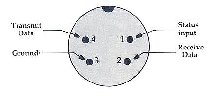
The four-pin RS-232 port on the Color Computer has only the so-called "minimum configuration" RS-232 signals (see Figure 1), but this is still more than most other computer manufacturers provide. You can therefore avoid many of the usual difficulties when interfacing a printer.
Figure 1:
Standard Designations For Serial Port Pins
When you want to connect a printer to your 'I'RS-80, the path of least resistance is to use one of the three Radio Shack printers which are directly compatible with the Color Computer. The DMP-100, DMP-200, and DMP-400 are dot-matrix printers which include a switch-selectable, four-pin serial interface in addition to the usual parallel interface. So, adding one of these models is as easy as connecting a four-pin (DIN) to four-pin cable between the printer and the Color Computer serial port. These cables are available at Radio Shack or, if you're a hardware hacker, you could pick up the parts at a local electronics supply store and easily construct your own.
One Bit At A Time
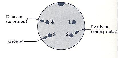
If you wish to attach another brand of printer, keep in mind that the Color Computer has only a serial (one bit at a time) interface. Many printers come equipped with parallel (eight bits at a time) interfaces. Before you spend several hundred dollars make sure that the printer you are buying has an RS-232 serial interface or that one is readily available for your particular model. Another thing to keep in mind when interfacing to other printers is that, for some reason, the Color Computer ROM printer output routines assign uses to the pins of the serial port that do not match their own stated standard designations (see Figure 2).
Figure 2:
Pin Designations For Use With ROM Output Routines
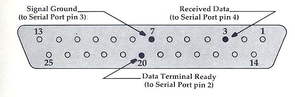
The printer's serial interface will most likely have the standard DB25 plug. This is the connector most commonly used in RS-232 communications, and a particular RS-232 signal is assigned to each of the pins on the plug. As an example, Figure 3 shows the connections necessary to connect an Epson MX-80 or MX-100 (with RS-232 serial interface) to the Color Computer. These same connections should work for other printers, but you should check the pin designations in the manual for your particular printer to be sure.
Figure 3:
DB25 Connector On Printer RS-232 Interface
How To Activate Your Printer
If you have Extended BASIC on your Color Computer, you can format your output with the PRINT USING statement. For example, this line:
20 PRINT #-2, USING "$$###.##"; 293.687
should cause the printer to print
$293.69
Another Extended BASIC function you can use with your printer is POS. This returns the current print position. For example, PRINT POS(-2) will tell you the column in which the next character will be printed.
A number of the Radio Shack software packages support printer output. Naturally, the Color SCRIPSIT word processing program includes the capability to print out text. The Speculator electronic spreadsheet program enables you to print out your worksheets. Other programs which support printout include the Personal Finance and Editor/Assembler programs. The Graphics Pack program supports printout to the Radio Shack CGP-115 color graphics printer. This printer is good for multicolor graphics applications, but only marginally useful for printing text.
Matching Specifications
You should consult the manual for your printer and set the appropriate DIP switches (or whatever) to configure the printer to match these specifications. If your printer can't meet all the above conditions, several can be changed with POKEs to Color Computer memory locations. For example, the value in location 155 controls the print width. If you're using an 80 column printer, you'll want to include the following statement before using the printer:
10 POKE 155,80
The comma field width (location 153) controls the amount of space left between variables separated by commas in PRINT #-2 statements. The default value for this location is 16. Thus, the line:
40 PRINT #-2 "FIRST", "SECOND"
will cause the word "FIRST" to be printed beginning at the left margin, and the word "SECOND" to be printed beginning in column 16. You can adjust the value in location 153 to change the format of your printed output. If you change the print width or comma field width (locations 155 or 153), you should also change the last comma field (location 154). This location should contain the value of the print width, minus the comma field width. You can achieve this with:
15 POKE 154, PEEK(155) - PEEK(153)
Adjusting the rate of data transfer from the default value of 600 baud requires changes to the data in locations 149 and 150. The table below provides the necessary POKEs to location 150 for the given baud rates. (For all rates in the table, POKE 149,0.) This information comes from the TRS-80 Color Computer Technical Reference Manual (pages 38 and 39), which provides further details on interfacing printers to the Serial Port.
Adjusting The Rate Of Data Transfer
| Desired baud rate | Value to POKE into location 150 |
|---|---|
| 300 | 180 |
| 600 | 87 |
| 1200 | 41 |
| 2400 | 18 |