Bitmap Graphics On The 64
Michael Tinglof
High-resolution graphics are achieved by bitmapping. Here's a tutorial and an explanation of what happens in the 64's memory as you bitmap. Also included is a sample program which illustrates the techniques discussed.
High-resolution images of 320 by 200 point (called pixel) resolution are possible on the 64. To create these images, the 64's VIC-II video chip uses a technique called bitmapping. Simply defined, this means that every bit in a selected area of memory represents one pixel (the smallest point of light) on the high-resolution screen. Thus, by setting or clearing appropriate bits, a picture can be formed.
You might ask "Why use bitmapped graphics when sprites are available and far more convenient to use?" The answer is simple: Each graphics mode has its own purpose. Several of the main reasons for using bitmapped graphics are to create graphs of formulas or statistics, to create high-resolution color pictures, and to create a detailed background for use with sprites, such as for a game.
Binary Operations
Before the bitmapped mode can be used effectively, it is important to have a basic understanding of binary arithmetic (see the section "Binary And Bitmapping" accompanying this article) and the logical AND and OR commands. Basically, they are used to selectively set and clear one or more bits in a byte. AND and OR cause a bit-by-bit comparison of two bytes to produce a third byte. In the case of AND, if both bits are on (1), the resulting bit is on; and in the case of OR, if either bit, or both, is on, the resulting bit, likewise, is on. For example:
| 10101011 | 00110001 | ||
| AND | 11011011 | OR | 10101010 |
| = | 10001011 | = | 10111011 |
The bits in a byte are usually numbered as follows:
7 6 5 4 3 2 1 0
AND is used to selectively clear bits, and OR is used to set bits. For example:
Given: 10100101, clear bit 5. To do this, define a byte with bit 5 set (0010000), then take the inverse (properly termed "complement") of the byte by changing all l's to 0's and vice versa. Finally, AND the calculated byte with the given byte:
| 10100101 | (given) | |
| AND | 11011111 | (calculated) |
| 10000101 |
Given: 10100101, set bit 6. To do this, define a byte with bit 6 set. Then OR this byte with the given byte:
| 10011010 | (given) | |
| OR | 01000000 | (calculated) |
| 11011010 |
Remember that when BASIC is used, all binary bytes must be converted to decimal first. BASIC'S AND or OR instructions will then work as described above.
Setting Up The VIC-II Chip
With an understanding of ANDs and ORs, a high-resolution picture can be created. The first step is to select an area of memory 8,000 bytes in length for the bitmap.
The VIC-II chip accesses only one 16K block of memory at a time. Upon power-up, the VIC-II sees the first 16K from locations 0 to 16383. All video operations, including those for screen memory and sprite definitions, access the memory in this area. There is no room in this block for an 8K bitmap, however, without conflicting with BASIC. The best solution is to select a different 16K block. (Bits 1 and 0 of address 56576 control where the block is placed in memory.) The combinations of these two bits and the range of addresses they represent are as follows:
| decimal | binary | address |
| 0 | 00 | 49152–65535 |
| 1 | 01 | 32768–49151 |
| 2 | 10 | 16384–32767 |
| 3 | 11 | 0–16383 |
Note that each block starts at an even 16K boundary. To select a memory block for the VIC-II chip, use the following command:
POKE 56576, Y
where Y is one of the decimal values from the above table. The best block to choose when using a bitmap and BASIC is number 2:
POKE 56576, 2
Within this block, two more areas must be selected: one for the 8K bitmap and one for the 1K screen memory. Address 53272 is used to control these two memory regions. One bit in this byte controls which 8K section in the 16K block is used for the bitmap; four bits control which 1024-byte area is used as the screen memory; and three bits are not used. The bits are arranged in address 53272 as follows:
| 7 6 5 4 | 3 | 2 1 0 |
| screen memory | bitmap | X X X not used |
The areas selected must fall on even boundaries — that is, their starting address must be a multiple of their size. For example, if the 16K block selected is from 0 to 16383, the screen memory can fall on 0, 1024, 2048, 4096, and so on. The following table can be used to determine which block should be used for screen memory or the bitmap:
| Base plus | screen memory block | bitmap block |
| 0 | 0 | 0 |
| 1024 | 1 | |
| 2048 | 2 | |
| 3072 | 3 | |
| 4096 | 4 | |
| 5120 | 5 | |
| 6144 | 6 | |
| 7168 | 7 | |
| 8192 | 8 | 1 |
| 9216 | 9 | |
| 10240 | 10 | |
| 11264 | 11 | |
| 12288 | 12 | |
| 13312 | 13 | |
| 14336 | 14 | |
| 15360 | 15 |
where Base is the first address in the selected 16K block. To set 53272, use the following formula:
POKE 53272, screen memory block * 16 + bitmap block * 8
If you are using the bitmap and BASIC at the same time, use the following POKE:
POKE 53272,120
This sets the screen memory block to seven, and the bitmap block to eight. For the 16K block suggested for use with BASIC, this means that screen memory starts at 23552 and the bitmap starts at 24576.
Once the memory pointers have been set, the VIC-II chip must be told to display the bitmap on the screen. Bit 5 of 53265 turns on the bitmap mode, that is, displays bitmap memory. To set this bit, use the following POKE command:
POKE 53265, PEEK(53265) OR 2↑5
Drawing The Picture
A high-resolution picture can now be created — all you have to do is set and/or clear the appropriate bits in bitmap memory. The problem is determining which bit controls which pixel. This requires an understanding of how the VIC-II chip draws the bitmap on the screen.
The bitmap memory is constructed similar to screen memory in text mode — it is broken into 1000 areas, each eight bytes in size, which we'll call cells.
These cells are arranged contiguously in memory — cell 1 follows cell 0, cell 2 follows cell 1, and so on. They are arranged in the bitmap in an order similar to that of screen memory in the text mode, 40 cells per row, 25 rows. The whole process, as described so far, can be illustrated as follows:
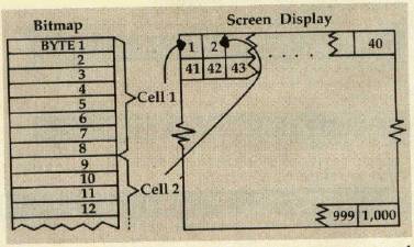
Each cell controls an area of 64 pixels arranged in an 8 by 8 matrix. The first byte in the cell controls the top row of pixels in that matrix, the second byte controls the row beneath, and so on down.
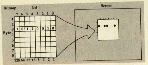
The eight bits in each byte control one pixel in that row — the highest valued bit controls the leftmost pixel and so on through the lowest valued bit, which controls the rightmost pixel. Graphically, the process works as follows:
Using X and Y coordinates is cumbersome with this system. If this type of plotting is needed, the following equations will determine which bit to set for the X, Y coordinate:
Y1 = INT(Y/8)*8 determines which row of cells X1 = INT(X/8)*8 determines which cell on the above row AD = Y1*320 + X1 + Y - Y1 + start of bitmap memory determines address of proper byte BT = 7 � X1 determines which bit to set POKE AD, PEEK (AD) OR 2 ↑ BT sets the bit
If you have been following our example setup commands, use a starting address for the bitmap of 24576.
Adding Color
Color is an important part of high-resolution graphics. Each of the 1000 bytes in screen memory controls the color displayed for one cell. Note that screen memory controls the color only in bitmap mode — in normal text mode, it contains the characters displayed on the screen. The bytes in screen memory are in the same order as the cells in the bitmap (the color of cell 650 is controlled by byte 650 in screen memory). In each byte, four bits are used to control the color of each bit in the corresponding cell of the bitmap, and four bits are used to control the color of bits equal to zero. These bits are arranged in each byte of screen memory as follows:
| 7 6 5 4 | 3 2 1 0 |
| color of bits = 1 | color of bits = 0 |
The colors and their corresponding values are listed on page 159 of the User's Guide. Once the values for the desired colors have been found, use the following formula:
(color of bits = 1)*16 + (color of bits = 0)
POKE this value into the appropriate byte of screen memory. Remember that attempting to change the color of one pixel will change the colors of all pixels in that cell of bitmap memory.
Note that screen memory for our working example begins at address 23552.
Recall that this method can be used to create a picture with 320 by 200 pixel resolution. Another bitmap mode is available, however. This second mode allows four colors in each cell rather than two colors as demonstrated above. There is one catch: resolution is reduced to 160 by 200 pixels, and each pixel is twice as wide. The multicolor mode is enabled by turning on bit 4 of location 53270. Use this command to enable multicolor mode:
POKE 53270, PEEK(53270) OR 2 ↑ 4
Each pixel is now represented by two bits. These two bits have four possible combinations, resulting in four possible colors. To find the color each bit combination represents, several memory locations and/or areas are accessed: screen memory, color memory (this is always from 55296 to 55319), and the background color register at 53281. Color memory is arranged in the same order as screen memory. The following chart shows which bit combinations access which areas of memory:
| Bit Combination | color from |
| 00 | background register (53281) |
| 01 | screen memory (4 bits of greatest value; same as bit equal to one in two-color mode) |
| 10 | screen memory (4 bits of least value; as bit equal to 0) |
| 11 | color memory |
Remember that three of the four colors selected can be different for each cell in the bitmap. The method used to draw the bitmap on the screen in two-color mode is used in the multicolor mode — only now, the bits are grouped together into pairs. The pairs are formed sequentially, so that bit 7 and bit 6 are paired, bit 5 and bit 4 are paired, and so on.
Protecting Your Picture
When using BASIC and the bitmap modes together, BASIC may have a tendency to use the bitmap memory for program and/or variable storage. To prevent this, change addresses 55 and 56, the bytes which point to BASIC'S end of memory. Simply change these to point to an address below the lowest address you use. Address 56 is equal to the last address used divided by 256, and address 55 is the remainder. After changing these two bytes, execute a CLR instruction. For example, this instruction insures that BASIC will not use any memory after address 23552:
POKE 55, 0:POKE 56, 92:CLR
To restore your 64 to normal operation, use the following commands:
POKE 53265,27:POKE 53270,200:POKE 53272,20: POKE 56576,151
BINARY AND BITMAPPING
Lance Elko, Assistant Editor
The Commodore 64's high-resolution graphics screen consists of 64,000 (320 by 200) dots or pixels. Each one can be turned on or off to let you create your own special graphics. This technique is called bitmapping.
At first glance, you might think that if there are 64,000 pixels to control, you'll need to use 64,000 memory cells (bytes) — but this would use more memory than you have available. With bitmapping, one byte controls not one, but eight pixels. Since there are eight bits (a bit is the smallest unit of storage in the computer's memory) in one byte, each bit represents one pixel on the hi-res screen. So, only 8,000 (roughly 8K) bytes are needed for bitmapping. Let's see how the computer handles these bits and bytes.
Filaments And Light Bulbs
Computers use the binary numbering system rather than the decimal system we're used to. A good way to understand how binary works is to think of a row of light bulbs, each capable of being on or off. The row has eight light bulbs and represents a byte; and each bulb represents one bit. If they are all off:
00000000
we have a value of zero. Now let's turn on the right one:
00000001
This gives us a value of 1. So far, it's not at all tricky.
The next bulb, counting from the right, however, has a somewhat different construction: It has two filaments. If just this bulb is on, it is indicated as:
00000010
but, remember, this bulb has two filaments, so the value here is 2. Let's go back and turn on the first bulb, also:
00000011
We now have a value of 3. Two bulbs are on, but three filaments are lit. The next bulb, the third from the right, contains four filaments (twice the number of the last bulb). So, if this is turned on:
00000100
we have a value of 4. If we turn on the previous bulbs:
00000111
we have 6 (4 + 2 + 1) filaments, but only 3 bulbs turned on. The binary value of 00000111, then, equals the decimal value of 6. We can see a pattern emerging here: Each bulb has twice the number of filaments as the one before it:
00000001 = 1
00000010 = 2
00000100 = 4
00001000 = 8
00010000 = 16
00100000 = 32
01000000 = 64
10000000 = 128
Converting Decimal To Binary
On/off combinations of these bulbs will yield any number between 0 and 255 (11111111). Let's pick a number, say 209, and figure out how to represent that number in binary. In other words, if we need exactly 209 filaments lit, which light bulbs should we turn on?
Since we can get 128 of them out of the way, let's do that first:
10000000 (128)
If we add the next available light bulb, with 64 filaments, that will get us up to 192 (128 + 64):
11000000 (192)
Now, we can't use the next bulb (with 32 filaments) because that would exceed our requirement of 209; so let's check the next one, 16. We can turn this one on because it would get us closer to our goal without going over (192 + 16 = 208):
11010000 (208)
We need only one more to make 209, and that's easy because there's only one bulb with one filament, the first one we discussed. Let's turn this one on:
11010001(209)
and now we have 209 filaments turned on with only 4 light bulbs.
How does all this apply to bitmapping? The VIC-II chip, a microprocessor in the 64 that controls video display, scans an area of memory reserved exclusively for bitmapping. The chip reads each bit in every byte in this area, looking for 1s (on) and 0s (off). When a 1 is noted, the pixel it represents is turned on, and when a 0 is noted, the pixel remains the same as the background color.
Keeping in mind these points about binary numbers, take a look at Michael Tinglof's article to see how to control bits and bytes for effective bitmapping. He also discusses special commands used for manipulating the binary figures we discussed. You might find pages 121 — 28 in the Commodore 64 Programmer's Reference Guide helpful as well.
A Graphics Demonstration
If all the computations needed to find the right bit seem complicated to you, and the two-color mode would be satisfactory, use the following utility program. It is written in machine language to increase speed, and can be used through X and Y coordinates. It is accessed from BASIC via the SYS command.
The format of the SYS call is as follows:
SYS (base address of code), command, operand(s)
The commands for the utility are as follows:
- 0 = clear bitmap page (set all bytes to 0)
- 1 = set screen color. Set all bytes in screen memory to the operand. For example, SYS(BS), 1, 32 sets every byte in screen memory to 32.
- 2 = set point. Set a given point according to its X and Y coordinates. Note that the upper-left corner is (0, 0) and the bottom right is (319, 199). For example, SYS(BS), 2, 28, 122 sets point (28, 122).
- 3 = clear point. The format is the same as above.
This machine language utility is relocatable and can be loaded into memory anywhere simply by changing the pointer in the BASIC loader. Before the utility can be used, however, addresses 680 and 681 must be set. Set address 680 to the start address of the bitmap divided by 256. Likewise, set address 681 to the start address of screen memory divided by 256. If you have set up the bitmap as shown in our working examples, use these POKEs:
POKE 680, 96:POKE 681, 92
To see how the utility and various aspects of bitmapped graphics work, look at the following program, which draws a sine curve on the screen.
Bitmapped graphics are a powerful part of the 64's repertoire. Once mastered, the results can be spectacular. Remember, the best way to learn is by hands-on practice. Once you feel comfortable with the techniques we've covered, try some of these ideas:
- Draw the picture into memory, then switch the pointers to it. This makes the graphics appear lightning fast, even from BASIC.
- Use several bitmaps and switch the pointers between them. Again, this gives the appearance of lightning fast graphics.
- Use sprites. Since the sprites are totally independent of the background, you can create some fantastic graphics for games.