COMMUNICATION!
Dann McCreary
While both the 1802 and the 6502 can handle quite a bit on their own, each has features which suit it to certain functions. Though the 1802 is not particularly fast, it has the advantages of low power consumption and low parts count needed to make a compact, portable system. On the other hand, the 6502 has the speed and software support for use as a powerful general purpose computer. Let's take a look at some ways to start a dialogue between an 1802 and a 6502.
Consider with me a few possible uses and layouts of COSMAC systems in communication with a central 6502 processor. One situation is the use of an 1802 to gather data from a remote location. The data would typically be transmitted to the main computer over a serial data link. This could take the form of a twisted wire pair, a radio transmission, a modulated light beam, telephone lines or even an intermediary like magnetic tape.
Another possibility is parallel communication. This would be used at closer range to achieve higher data rates. A parallel interface transfers an entire byte of data at a time. Some form of handshake is employed to coordinate the transfer timing. A portable 1802 unit might be brought and plugged into a central computer for a rapid transfer of data.
Perhaps the fastest and most direct communication between 6502 and 1802 could be obtained by combining the two processors as co-processors with common access to at least some memory regions. This would make possible the sharing of some tasks between the two processors. By setting or clearing specified bytes of shared memory, data might be passed from processor to processor and the activities of both coordinated.
Let's look at some serial data formats and the software considerations for producing them. The basic principal behind serial communication is to take a signal capable of presenting two states, 1 or 0, high or low, and to vary that signal in a specific time dependent pattern. This can be done readily by incorporating a UART such as the 1854 in your 1802 circuit. The 1854 is a CMOS UART (Universal Asynchronous Receiver / Transmitter). It has all the necessary circuitry on one chip for generating and interpreting serial data streams on a character by character basis. When connected to an 1802, the 1854 makes sending serial data as easy as outputting a byte of data to a selected port.
In the interests of keeping our 1802 system small and simple. However, let's do the following: we'll look at a way to use the Q line of our 1802 as a serial data output, and one of the External Flag lines as a serial data input. This eliminates the need for a UART, but it shifts the burden over to software.
What are the elements of serial data transmission that we must create by programming? Look at the illustration of an 8 bit data word in serial format. At the beginning of the word, the serial line is in a high (1) state. This high state is of an indefinite period of time. Transmission of the word is begun by bringing the line low for one bit-time. This is called the start bit. It is in effect saying, "Get ready guys-here comes the data!". The bit time is based on the desired data transfer rate, or "baudrate".
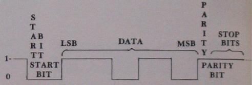
Following the start bit are 8 data bits, each using one bit-time. The first bit transmitted is the least significant bit of the data word. After the data bits comes a final parity bit. Finishing the transmission of the word are the stop bits. Stop bits are always 1 (high). For best reliability, 2 stop bits are recommended. This gives a receiver a fighting chance to synchronize itself with a continuous stream of data words. If a data word is not sent immediately, the line just remains high until the start bit of the next data word is sent.
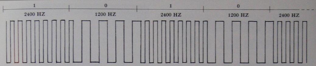
For a variation on the theme, what if we wish to store the data on audio magnetic tape? We can use a very similar serial data format by superimposing audio tones onto our high and low segments of the signal. That is, let a high frequency tone represent a "1", and a low frequency tone a "0". The "Kansas City Standard" cassette format does in fact use this method. It differs from the above format only in that it does not use a parity bit. Each "0" consists of 4 cycles of 1200 HZ and each "1" consists of 8 cycles of 2400 HZ (see illustration).
Let's write a routine for generating either a straight serial data format or an audio-modulated cassette format. We'll set it up as a subroutine which, when called, will transmit the data in the "D" register in a serial format via the "Q" output flip-flop. We'll design our subroutine to allow for variation in the number of data bits. Parity will be settable as odd, even or completely off. The subroutine will also allow for either straightforward serial format or else audio-modulated serial format for use with a magnetic tape or telephone line transmission. In our next 1802 column, we'll examine some COSMAC code which will accomplish all this for us.