|
The Artist
& the Computer
by Pam Sexton
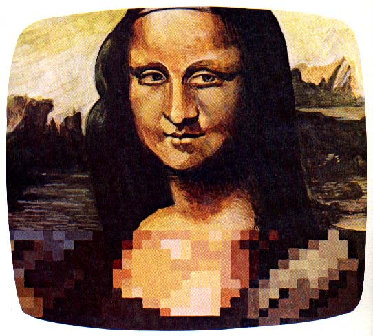
We've all been told that a painting is best viewed from a distance, but to understand the finer details of an artist's technique requires a closer scrutiny. Some "Old Masters" are even studied using magnifying lenses.
If your interest in television graphics is purely for enjoyment, you can sit back and appreciate its color and design. If, however, you'd like to understand the graphics display, you'll have to move closer to the screen. This series of articles will take you closer to the screen.
First, let me introduce you to some vocabulary that is fundamental to graphics and microprocessors in general.
Pixel. Imagine your monitor is overlaid with a sheet of graph paper designed to fit exactly on the screen. We are interested in the little squares that fit together to create the paper. Each one of these squares is a pixel.
Binary. Anything binary consists of only two parts. In a binary world, we see only black and white. Statements are true or false. Inside a microprocessor are two conditions: on or off. A zero (0) indicates an off condition; one (1) indicates an on condition. The microprocessor is a binary world of 0's and 1's.
Bit. A contraction of "binary digit." A bit is either a zero or a one.
Byte. Humor does exist in computerese. Take a handful of bits--0's and 1's--until you have hold of eight of them. Line them up in any pattern you choose. You then have a byte, a group of eight digits.
Register. An area reserved in a computer to hold a designated value. For example, a color register is used in the Atari 800 to hold a value that represents a certain color.
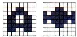
Character. An image that is defined by turning "on" or turning "off" pixels in a pattern within an eight-block wide by eight-block deep square or "matrix." (Eight digits across equals one byte; each matrix is eight bytes deep.) For example, the letter A and the image of a starship are formed as follows:
|
| Fig. 1. 8 x8 Matrix pattern of the letter "A" (left) and Star- ship image (right). |
The Atari Character Set
The operating system within the Atari 800 supplies a standard character set. These are the familiar keyboard images: alphabetical characters and special-purpose characters such as the dollar sign ($) and equal sign (=). The full character set contains 128 characters. But, as a computer graphics artist, you are not "locked" into this character set. You have the option of creating up to 128 of your own unique graphics patterns and replacing the standard character set. To do this you must use that portion of memory reserved by the operating system for its alphabetical characters.
To use the Atari character graphics you must:
- Define the character set
- Convert the graphics images into computer data
- Display the image onto the television screen.
As expressed previously, a character consists of pixels placed in a pattern on an 8x8 matrix. With this restriction, you may initially feel that your artistic attempts are somewhat confined. Not to worry. Begin with a large sheet of graph paper dimensioned in some multiple of eight, for example, 32 x 32 squares or 512 x 64 squares. Sketch an appealing image on the paper. After you have finished your drawing, divide the paper into 8 x 8 squares.
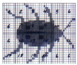
To demonstrate, I'll be a little less industrious and use a sheet of graph paper dimensioned to 48 x 32. That gives us 24 possible characters (See Fig. 2).
|
| Fig. 2. Black and white character set graphic of a beetle bug. |
Remember our discussion of a binary world where everything is either black or white, on or off?. Take a look at each square of the drawing. Whenever you encounter a square that is to be colored, assign it the value 1. And, likewise, whenever you run across a square to be left blank, assign it the value 0. Encoding the first 8 x 8 block in Fig. 2, produces the following result.
0 0 0 0 0 0 0 0
0 0 0 0 0 0 0 0
0 0 0 0 0 0 0 0
0 0 1 0 0 0 0 0
0 0 0 1 1 0 0 0
0 0 0 0 1 1 0 0
0 0 0 0 0 0 1 1
0 0 0 0 0 0 0 0
Adding Color to the Beetle
Let's interrupt our discussion momentarily to introduce another element. This black and white environment is less than pleasing. By adding one more color, say a red-orange, you can transform the ominous-looking beetle in Fig. 2 into a more glamorous ladybug. But, how can you do this if you're restricted to a binary system?
It's time to fine-tune our character definition. A character is an image defined by lighting pixels in a pattern within an 8-bit by 8-byte matrix. When dealing with a two-color image, a single bit can define the color for a pixel. Therefore, the width of a character is eight pixels. However, when you are dealing with more than a two-color image, you must use a two-bit combination to define the color for a specific pixel. And so, the maximum character is now limited to a four-pixel (four-block) width.
Using Atari Basic you can assign colors to any of four color registers. You access the color as you need it by referring to the register that contains the color value. This process is known as "indirection."
Think of these registers as an artist's palette, and imagine the Basic program statement as the artist's brush. Every time the artist dips his brush into the color in the upper left corner of the palette, that color ultimately appears on the canvas. If the artist dips his brush into the color in the lower right corner of the palette, then that color appears on the canvas.
Imagine that an artist's palette can hold only four containers of color at once. He now has to hire an assistant who will run around and exchange containers to provide the artist with more colors. In the Atari this artist's assistant is our Basic Setcolor statement. The Setcolor statement calls a color from the appropriate registers. The color registers in the Atari are labeled Playfield 0 through Playfield 3 and Background. Basic can access only four of the registers at any one time.
|
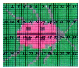
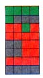
| Fig. 3. Three-color character set graphic of a ladybug. |
The Atari operating system assigns a specific combination of bits, a bit pattern, to indicate a particular color register.
Returning to our example, let's place black in Playfield 0 and use this register to color in the legs and antenna. And let's place green in Playfield 1 and use this as an outline color for our graphic display. Finally, let's place a red-orange in Playfield 2 to transform our ladybug. Using the bit-pattern in Table 1, our drawing now looks like Fig. 3.
| Bit Pattern | Register | |
|---|---|---|
|
00 01 10 11 |
COLBK PFO PF1 PF2 |
Background color Playfield 0 Playfield I Playfield 2 |
Table 1. Bit Pattern to Register Assignments
Let's code Character Number 11 in Fig. 3.
                  10 10 10 10
                  10 01 01 01
                  11 11 01 11
                  11 11 11 11
                  01 01 11 11
                  01 01 11 11
                  11 11 11 11
                  01 01 01 01
Fig.4. shows the three-color pattern for character number 11.
|
| Fig. 4. Character Number 11 from the colored ladybug. |
Binary Conversion
Because Basic requires decimal data, you must now convert the binary pattern into decimal equivalency. The eight binary digits of any byte correspond to an exponential power of 2.
The rightmost bit of any byte sits in the 2 to the 0 power position, and the leftmost bit lies in the 2 to the 7th power position (Fig. 5).
|
|
||||||||
|
Fig. 5. Binary to decimal conversion of an eight-digit byte.
|
2 0 = 1 2 1 = 2 2 2 = 4 2 3 = 8 |
2 4 = 16 2 5 = 32 2 6 = 64 2 7 = 128 |
To convert the binary pattern of 0's and 1's to decimal means that you add the powers of two in those positions containing a one and disregard any position of zero value. So, the first byte in Character Number 11 looks like Fig. 6.
|
||||||||
|
||||||||
|
||||||||
|
Fig 6. The appropriate power of two is added where the digit one is in Position.
And the second byte equals 149 (Fig. 7).
Continue to obtain the decimal equivalents for all your characters. To complete the example, the remaining bytes are 247, 255, 95, 95, 255, 85. This is the most time-consuming task related to character design.
|
||||||||
|
||||||||
|
||||||||
|
Fig. 7. The second byte in Character Number 11 equals 149 decimal.
Displaying the Image
By entering Program Listing 1 you can display the example ladybug graphic. Several elements enter into this program:
- Choice of colors
- Position of the display
- Sequence of characters
- Display list instructions
- Choice of graphics mode
- Position of the data in computer memory
In the next article, I will go into the detail of Program Listing 1 and provide you with enough information so that you can display your own character graphics. Meanwhile, I invite you to work on your character set, and prepare for programming and animation!
NOTE: Line 1 of Program Listing 1 is created as follows. ?"[ESC] [CTRL. DOWN ARROW] [ESC][CRTL.DOWN ARROW] [ESC][CTRL.DOWN ARROW] [ESC][CTRL.DOWN ARROW] [ESC][CTRL.DOWN ARROW]" The purpose of this line is to move the cursor below the ladybug so that it will not interfere with the graphic. The CTRL and Down Arrow keys are together in brackets to signify that they should be pushed simultaneously.
Listing: COMPUART.BAS Download