FEATURE
Software Evolution
From Art to Engineering
by Karl E. Wiegers
Long ago, in a galaxy far, far away, people began to program computers. At that time, the computer itself was a room-filling monstrosity, and the programming challenges were quite different from those of today. Everything was done at a machine language level, which is dandy for computers but a bit taxing on the human eye.
Not so long ago, in a nearby galaxy, people started programming in assembly language, and then in third-generation ("high-level") languages such as FORTRAN, COBOL, and PL/I. The programs became larger as the machines shrank. Unfortunately, the software problems became larger, too, and some interesting trends began to emerge.
Large software projects were nearly always completed over budget and late, if at all. The danged users kept changing what they wanted, and the over-taxed programmers could scarcely keep up with them. Hence, programs were forever being altered after they were declared complete. In fact, data-processing departments were spending several times the dollars and man-years that they anticipated for program maintenance (adding enhancements, fixing bugs, and changing to conform to current user requirements).
Just yesterday, in the galaxy right next door, the microcomputer was invented. This opened the world of computing to a whole new generation of amateurs: hackers, if you like. We were back to assembly language, although Bill Gates soon opened the floodgates of high-level languages by introducing the first BASIC interpreter for micros.
Now, hackers tend to be an independent lot. (For an informative and entertaining historical perspective, read Hackers, by Steven Levy.) In the early days, clever microcomputer programmers taught their machines how to sing, dance, and show pretty pictures. They were more concerned with the latest animation techniques than with writing structured, maintainable code. And, hey, with only 16K or so to work with, you can live with that. But again, the computers got smaller, cheaper, and more powerful at an astounding rate, and the programmers only slowly figured out better ways to create the code that rapidly expanded to fill all available RAM.
Today, on our very own planet, there is a widely recognized "software crisis." The rate of progress in software development hasn't begun to keep pace with that of the rapidly evolving hardware on which the programs run. The expectations of users have gone up, and software customers often are dissatisfied with the final product they acquire. The quality of the software often leaves something to be desired. Maintenance has become a major issue: look how many different releases of commercial packages appear and the fresh problems that crop up with each new version. And the developers frequently don't have a good idea of how long it's really going to take to get the next product out the door. The result is vaporware.
In short, we can no longer afford the luxury of computer programming as art, except for those who still view programming mainly as an exceptionally intriguing hobby and learning experience. To make a buck with software now requires a more systematic, rigorous, and structured approach, akin to that used for producing the computers themselves. The old generation of computer programmers as independent artists is (slowly) giving rise to a new generation of "software engineers."
Is this really such a big deal? Well, consider that IBM estimated the world-wide costs of software development and maintenance in 1986 to be some $135 billion. That's a fair piece of change. And while computing hardware has been growing in speed and power at a rate of around 30% per year, software development productivity seems to be increasing at only about 4% annually.
Yes. It is a big deal.
Wherefore Software Engineering?
Software is just like hardware, only completely different. Hardware (meaning machines of any kind) can wear out; software can't. (Of course, the floppy disk can wear out and the software can become obsolete, but these are hardware and business problems, respectively.) Hardware can be rigorously tested to make sure it works right under specified conditions—it can be stressed. There's no way to exhaustively stress-test most software. Once in place, hardware is difficult and expensive to update, whereas software can be changed much more readily, at least from the user's point of view (think of the contents of a book versus the contents of a floppy disk).
Here's a simple hardware/software comparison you can do in the privacy of your own mind. When was the last time you asked the Maytag man to come out and add a variable speed option to the spin cycle on your washing machine? Now, when was the last time you sat at a keyboard and said, "Gee, the next version of this program is supposed to be able to. . . ."
Despite these differences, the software development sequence does have a well-defined life cycle, quite similar to that of hardware development. The historical view considered the software life cycle to consist of steps to analyze the problem, design a software solution for the problem, write the required programs, test the system, install it, and maintain it. The goal of software engineering is to provide a more controlled approach to the software life cycle that will facilitate the efficient development of higher quality products than was possible using earlier methods.
Here's an irony for you. The hardware business has been revolutionized by the techniques of computer-aided design (CAD), engineering (CAE), and manufacturing (CAM). Doesn't it seem strange that the software industry is still so dependent upon the individual efforts of individual human beings?
The software engineering philosophy does emphasize the use of automated tools to facilitate the program development process. Such tools include computer-aided software engineering (CASE) products, as well as programming environments and utilities optimized for productivity. The latter include such things as syntax checking program text editors, powerful compilers, linkers and debuggers, and usability environments like GEM.
But tools of any kind are only useful if they are applied in the context of a systematic methodology. Several software engineering methodologies (or "paradigms," if you want to baffle your friends and alienate your in-laws) have evolved in recent years. Some of these involve graphical "languages" for the structured analysis and design of software systems. We'll talk about some of these later on.
Another aspect of software engineering is the development of procedures for managing and monitoring the technical activities involved in program development. For example, how do you measure the productivity of a software engineer? With hardware, it's easier to measure productivity in terms of quantity (how many widgets?) and quality (did they all do their little widget thing right?). What does software quality even mean? And if you can't measure your productivity, how can you realistically project how long it will take you to complete a particular project? Tough questions, with no easy answers.
Software Life Cycles: Before
Many of you began your computing career with an 8-bit Atari of some sort. What was the "life cycle" of a program you wrote back then like? Well, you began with an idea. That was your planning step. You probably had a rough idea of how to proceed. That was analysis. If you are a particularly systematic person, you might have drawn out a flowchart, at least for the trickier sections of the program. That was the design step. But most of the time you skipped design and went right into coding, which consisted of typing your lines of Atari BASIC code as fast as you could into a single source code file, with perhaps a subroutine or two.
Testing consisted of typing RUN and observing what happened, then changing the lines that blew up (BASIC interpreters are great for sloppy. . .er. . .I mean casual program development). Installation consisted of giving a copy to a friend. Maintenance didn't really exist, partly because you were on to the next project, and partly because you didn't have any documentation (huh?) to remind you of what you did.
Don't try to lie to me about this; I've been there.
This unstructured, evolutionary programming approach works moderately well for smallish BASIC programs, but there are some problems, besides the obvious high chaos level. One is that your variables in Atari BASIC are all global; that is, they are known to all parts of the program. While this is convenient, it's also dangerous, because you can inadvertently use the same variable name for different purposes. Also, you are limited to single files of BASIC source code, since there aren't easy ways to join multiple files together. You can, of course, run one program from another, but you can't really link two smaller programs together to create a large one.
BASIC is not a highly structured language, making it difficult to partition a program into discrete, bite-sized pieces that fit together nicely. The lack of good selection logic statements (like IF/THEN/ELSEIF) makes it hard to adhere to the structured programming precept of each program having exactly one entry point and one exit point. I've seen spaghetti code mazes of GOTOs and GOSUBs that would turn your hair white. And the need for line numbers makes it hard to create libraries of useful subroutines to merge into different programs you might write. Did you ever try to squeeze some code in between lines 1304 and 1305? 'Taint easy.
Things in the Atari world have changed, along with the rest of the computer world. Modern languages for the ST, such as C, Pascal, and the newer BASICS like GFA and LDW, are more structured and modular. They let you write smaller program segments (called "modules") to perform specific functions, compile them separately, and link them together to create the runtime program. In the 8-bit Atari environment, Action! comes closest to being a modern, structured language.
Figure 1. Sample Data Flow Diagram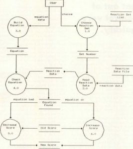
As memory became cheap and abundant, programs became big and complex. It's much easier to create and modify a small program performing a single function than a large monolithic program. The trick, then, is to break a large program into a bunch of small modules, each of which can be designed, coded, and managed easily. You build a large software system by fitting together lots of small modules like bricks. The mortar that binds the modules together is the data interface between each pair of modules. By precisely defining these data interfaces (variables passed, etc.), it becomes easy to reuse an existing module. Also, the information within each module can remain local to that one module, minimizing inadvertent variable changes that wreak havoc elsewhere in the program.
Software Life Cycles: After
The sequence of events involved in creating a large system in the software engineering mode is somewhat different from that followed in the days of yore. The advantages become especially great if there are several people working on the same project. Let's see how you might do things in 1988, using a software engineering approach.
1. Perform a thorough, structured analysis of the problem, including writing a complete list of specifications describing what the system is supposed to do. I'll describe what I mean by "structured analysis" in the next section. Make sure you are solving the right problem, and that you understand exactly what the program (or system of programs) must accomplish to be successful. The more complete the statement of requirements is, the more likely you are to come up with a satisfactory system.
2. Design the software system in detail before ever writing any code. Make sure the system you design is valid, complete, and can be implemented using the language(s) and hardware you have in mind. Believe me, it's much easier, faster, and cheaper to correct an error in the design than to fix the final product. Structured diagramming techniques can be used in the design step, and computer-aided software tools exist to help with this step (more about these later).
The hard part here is forcing yourself to hold off on coding until the design is complete. Face it, we all program computers because we love it. I've found it very difficult to discipline myself enough to avoid coding until I'm really sure of what I need to do, but it's usually worth the wait. Oh, all right, I admit it, I'll write snippets of code to try things out, but I call it "prototyping," so that's okay. (In fact, prototyping is an alternative software life cycle methodology that can be very effective, but that's a topic for another day.)
An important part of your design is to partition the problem into small enough pieces so that each program module is performing a single function. How you define "single" is up to you, but generally you want to try to limit module size to 100 lines of source code or less. Effective partitioning makes it easier to spread the work among different programmers. Also, you can identify modules that can be reused, either from a previous project or in the next project. This off-the-shelf-parts approach is another effective aspect of hardware engineering, and the payoff is just as great with software.
Each module should be designed to fit together with the others independently, essentially as a "black box" whose internal functioning isn't really important to other modules (or to people who use it as a part of another system, for that matter). Modules communicate through a well-defined data interface of passed variables and data structures. Try to avoid using global variables wherever you can, for the reasons mentioned earlier. Try to hide the data within each separate module from the other modules.
Figure 2. Sample Structure Chart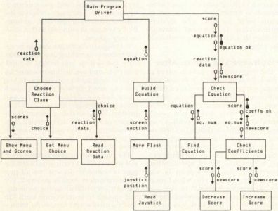
4. Okay, now you can write the program! Use good structured techniques, stick to the data interfaces described in the last paragraph, give your variables descriptive names, and avoid GOTO statements. Stick to the three main logical program building blocks of sequence (one statement after the other), selection (choosing one path from a choice, such as IF/THEN/ELSE or SELECT/CASE constructs), and iteration (FOR/NEXT type processing). Each module should have just one entry point and one exit point. These goals aren't always 100% achievable, but do your best.
There was an excellent series of articles about using structured programming techniques in BASIC way back in the May/July 1984 issues of the now-defunct Creative Computing magazine. The ideas apply to any language, although they are harder to implement in BASIC (or assembler—forget it!) than in newer languages. Any modern computer programming textbook will also describe structured programming principles.
5. Integrate the modules and test them to assemble the final, completed software system. If you do this right, you can fit the pieces together a bit at a time, either from the top of the program down or from the bottom up. Whole books can be written on software testing, so I won't go into detail here. Suffice it to say that all of us can do a better job of testing our products, by systematically going through a wide selection of test case input. Don't forget to look at the output. Just because the program didn't crash doesn't mean it worked right!
6. Document what you did, both in the source code (internal documentation) and in separate written form (external documentation). If you did a good job of design, much of your external documentation is already complete. Don't forget things like lists of the files involved, data file formats, etc. It's always important to include some comments in the source code about what the module is for, the details of the data interface for the module, variable and subroutine names and functions, and so on. Don't base your documentation on just what you see in published program listings, either. Some of it is very good, but much is too scanty for commercial-scale development.
But I Like to PROGRAM!
I know. The software engineering philosophy involves a lot of front-end effort before we ever get to the really enjoyable part of writing code. And for the casual programmer, who does this just for fun, it isn't worth the time to really do all the systematic groundwork that I described. But it works!
The first time I tried using structured program design methods, I felt that I enjoyed about a tripling of my efficiency. The quality of the programs you write will go up if you take even a limited engineering approach. And you'll really become a believer if you ever have to do any serious maintenance programming. The software engineering approach greatly simplifies the task of correcting or enhancing an existing program, especially if someone else wrote the original. Take it from somebody who's been there. The key word is "structure."
Structured Analysis and Design
In the olden days, flowcharts were often used for diagramming the logic of a computer program. While flowcharts are useful tools, they have some limitations. For one thing, they imply a sequence of events, by indicating how control flows from one operation to another. This might be okay for diagramming the internals of a module, but it doesn't work well for describing an overall software system, in which a different sequence (or even set) of events might take place each time the program is executed.
Figure 3. Sample Data Dictionary Entries
reaction-data-file = 7{reaction-data}
reaction-data = 16{chemical-formulas)
              + number-of-reactions
              + number-of-sets
              + 1{equation-description}16
equation-description = reaction-number
                     + 4{compound-numbers}
                     + 4{coefficients}
number-of-sets = [2|4]
English equivalent: The reaction data file consists of 7 blocks
of reaction data. Each block of reaction data consists of 16
chemical formulas, the number of unique reactions in the set, the
number of equivalent reaction sets, and from 1 to 16 blocks of
descriptions of the possible equations that can be formed. Each
equation description consists of a reaction sequence number,
compound numbers for the four compounds in the equation, and
coefficients for the four compounds in the balanced equation.
There can be either 2 or 4 equivalent reaction sets in each
reaction data block.
In the 1970's, several alternative methods were devised for so-called structured systems analysis and design. Many of these concentrate on the flow of data within a software system. After all, that's what software is all about. The most important question to ask during the analysis phase is, "What is the output of this system supposed to be?" The next question is, "What data do you need to generate this output and where does it come from?" Now that we have defined the outputs and inputs of the system (in that order), everything else is just a matter of transforming input data into output data. What could be simpler?
The most popular diagram used for both structured systems analysis and design is the "data flow diagram" or DFD. A sample DFD is shown in Figure 1. (The figures are all based on portions of an educational chemistry game I wrote once upon a time.) A DFD simply illustrates the relationships between all the pieces of a system; you shouldn't try to infer anything about the sequence in which various processes may be executed.
There are really only four kinds of elements in a DFD, each of which must be given an appropriate label:
- Processes—transform inputs to outputs. They are frequently represented as circles or rounded rectangles, called "bubbles." A process corresponds to a program module or group of modules.
- Data Store—repositories of data. They are shown as two parallel horizontal lines, and correspond to files, databases, or internal variable storage.
- Externals—entities outside the software system that communicate with the system, by passing data in or receiving data from the system. Externals (sometimes called terminators) are shown as rectangular boxes.
- Data Flows—data that moves between stores, processes, and externals. They appear in the DFD as lines with arrowheads that indicate which way the data is flowing. The data flow label indicates exactly what data is flowing. An unlabeled flow is assumed to have the same label as that of the data store to which it is connected.
Data flow diagrams aren't limited to software applications. They can just as easily be used to represent a system in which actual objects, not data, are flowing from one place (process, external, or store) to another. An example is a warehouse system, with, say, computer parts being moved about. The DFD is just a general way to diagram some system, without regard to the hardware or language that might ultimately be used for implementing a software system.
A data flow diagram is a "model" of the software system you are building. That is, it's a visual representation of the system that can be used to show the purpose of the system, how it connects to the rest of the world, and what components it is made of. The great thing about a model is that it's an awful lot easier to change the model than to change the real thing. Consider a three-foot scale model of an aircraft carrier. If you wanted to move the ship's island from the starboard side of the ship to the port, wouldn't you rather do that on the model before you built the full-size ship and said "Uh, oh."? I would.
DFDs are great for facilitating communication between the people who request a software system and those who have to create it. In this case, a picture is worth at least 1024 words. By obtaining very early a complete picture of what the system is intended to do, you are much more likely to come up with a final product that makes the user feel that his money is well spent. Structured analysis and design greatly reduce the chance of errors and oversights.
Unless your software system is very small, you can't squeeze a complete description of it into a DFD that will fit on one piece of paper (or one computer screen). Whatever shall we do? We'll break the problem into several levels, with increased detail shown at each successive level.
First, draw a DFD containing only one process, representing your entire system. This DFD is typically called a "context diagram," because it shows your system in the context of the rest of the world (all the externals that connect to the system). Then, use your microscope to peer inside that one process, and draw a second diagram containing several processes, representing the principal functions of your system. Each of those processes might be further expanded, showing even more detail, and so on.
This is the partitioning process I mentioned earlier. The ultimate goal is to subdivide the processes until each process on your lowest-level DFDs represents an individual program module that performs a single function. By drawing many DFDs at different levels, you don't have to try to comprehend the entire system by studying one mammoth diagram with many symbols and lines on it. A good rule of thumb is to limit each DFD to around seven or fewer processes.
Once you get your DFDs down to the module level, another diagramming method is used. "Structure charts" show the hierarchical relationships among modules, as illustrated in Figure 2. The structure chart also indicates the data interfaces between modules, by showing what information flows from a higher level module down to a lower level module and vice-versa.
Another vital part of the structured design is called the "data dictionary." How many times have you found that you used the same variable name to mean two different things in a program, or used different names for the same piece of data? Imagine the problems that can arise when several people are working on parts of the same program, with no rules as to what to name variables or files, or how large arrays should be, or what type of data each variable represents. Things can get out of control very quickly. It has happened to me, folks, and it could happen to you.
The data dictionary is a repository of definitions of all of the elements in the design, including data flows, data stores, processes, and terminators. It can avoid the redundancy of using different names for the same piece of data, errors and inconsistencies in variable names and characteristics, communication problems among programmers, and other related bummers. Of course, a data dictionary isn't much good if it's incomplete, inaccurate, or ignored. Figure 3 shows what some data dictionary entries might look like using one of the common notations (DeMarco's); the details aren't important here.
Now, we are almost ready to write the program modules themselves. But not quite. Our data flow diagrams tell us what information flows into each module and what flows out, but they don't tell us how to accomplish the transformation. The missing piece is a detailed "process specification," or "minispec." This design element describes exactly what goes on inside the module, in enough detail that now, finally, at long last, you can write a computer program in the language of your choice.
Process specifications can take many different forms. You have probably written them before, using some kind of "pseudocode" or "structured English" to write out in words exactly what you want the program to do. Figure 4 shows a process spec written in one flavor of pseudocode. Various other diagramming techniques can also be used, such as action diagrams, Warnier-Orr diagrams, and others. It's often a short journey from pseudocode or action diagram to actual code in a real computer language. In fact, some of the available computer-based diagramming tools will actually produce compilable source code from the diagrams, but such code generators are still pretty much a thing of the future.
This seems like an awful lot of junk to keep track of, just to write a computer program. Wait! Let's let the computer do the grunt work. Yeah, that's the ticket!
The Case for CASE
The latest items for your software engineering toolbox are CASE, or computer-aided software engineering tools. On one level, these are simply graphic editors, usually intended to be used on powerful microcomputer workstations such as the IBM PC/AT or Apple Macintosh. (Did someone say "ST?" Nope, not yet. Sorry.) Using a mouse, data flow diagrams, structure charts, and other diagrams used in structured systems analysis and design can be drawn.
But CASE tools are much more than simple drawing packages. Any CASE program worth its salt can make sure that your DFDs and structure charts are valid, in that they conform to the rules of some established diagramming methodology. Of course, it's the user's responsibility to heed the error messages and correct the diagram. You could always ignore the errors, but your aircraft carrier will look pretty funny if it's missing the flight deck due to a design flaw. Does the word "unemployment" mean anything to you?
CASE tools can integrate the data dictionary with the diagrams, automatically creating entries in the data dictionary when the DFDs are validated. They can detect inconsistencies in the way items in the dictionary are used or defined. They can make sure that each DFD is consistent with the related DFDs at higher and lower levels. They can verify that the data interfaces defined between modules in your structure charts are consistent. Some CASE packages can validate the structured English or action diagrams used in creating your process specifications. The overall goal is to reduce errors by ensuring that all the necessary parts of your design are present, properly defined, and properly connected. Doesn't this seem reasonable?
Summary
I hope you don't feel that all this talk about engineering is taking the fun out of computer programming; it doesn't have to. Most of us will always be hackers at heart, and we'll still spend time at the keyboard just typing things in and seeing what happens. That's the artist in each of us, fighting to get out and express himself electronically.
The main application for software engineering ideas, methodologies, and tools is in the world of larger-scale (usually commercial) software development, where projects tend to be increasingly complex and time-consuming. I think you'll agree that a free-form approach to serious program development isn't likely to be as successful as a more disciplined, systematic approach, particularly when several (or many) people are involved. Contemporary software products are expensive, they stick around for a long time, and they undergo continual revision and enhancement.
Figure 4. Sample Process Specification in Pseudocode
Procedure: Find Equation
Compare first compound number in equation with first compound number
   for all equations in set
If no match
   then call Error-Routine
   else if match then do
      compare other compound numbers in equation with those in
         entry matched
      if no match
         then call Error-Routine
      else if match
         then do
            get reaction number for matched entry
            if reaction number already complete
               then do
                  print "Already Done" message
                  make error sound
                  reset screen
               end do
            end if
         end do
      end if
   end do
end if
return
Procedure! Error-Routine
print "Incorrect Reaction"
make error sound
reduce score by 5 points
reset screen
return
As an example, I'm writing this article using ST Writer version 2.0. How many versions of this popular program has the good Dr. Noonan released to the Atari world? If Dr. Noonan didn't receive a structured design for ST Writer from the original programmers, I suspect he wishes he had by now. Software engineering can help prevent your program from ultimately becoming a crazy quilt of patch on kluge on repair on modification on correction.
Bibliography
There are many excellent books available on software engineering, structured design and development, and related topics. Here are a few of the best.
- R. S. Pressman, Software Engineering: A Practitioner's Approach, 2nd Edition, McGraw-Hill, 1987.
- R. S. Pressman, Making Software Engineering Happen, Prentice-Hall, 1988.
- T. DeMarco, Structured Analysis and System Specification, Prentice-Hall, 1979.
- J. Martin and C. McClure, Structured Techniques for Computing, Prentice-Hall, 1985.
- J. Martin and C. McClure, Software Maintenance, Prentice-Hall, 1983.