Inside ST Xformer II
A TUTORIAL ON WRITING FASTER 68000 PROGRAMS
by Darek Mihocka
About a year ago, ST-Log published the ST Xformer, an Atari 800 emulator whose inner workings I described in "Inside the ST Xformer" (ST-Log 17). At that time things seemed pretty well complete. The emulator worked—sort of—and I was satisfied that the assembly-language code making up the 6502 interpreter was well optimized—sort of. I knew of some places here and there where a few clock cycles could have been saved, but the savings wouldn't have amounted to much. The emulator ran at about 20% the speed of a real Atari 800, and it seemed that that was about as fast as it was going to go.
A few alert programmers who read the article and looked through my source code noticed a few more odd places where cycles could have been saved, but nothing that would have significantly sped up the emulator. But by now, most of you reading this know that ST Xformer II was released over the past summer, and it runs at an amazing 40% of the speed of an Atari 800—100% faster than the previous emulator.
A faster interpreter
How was it done? What happened between the summer of '87 and the summer of '88 was that I learned a lot more about 68000 machine language than I really ever wanted to. As most programmers know, if you want to optimize a high-level program, you rewrite it in assembler. But if you want to optimize an assembler program, you have to find a better algorithm. And if that doesn't work, cheat! That's what I did with the Xformer II.
I learned quite a few good 68000 tricks, and I'll cover them all in this article. One important fact about the 68000 is that because of its orthogonal design, there are usually many ways of getting it to perform the same task, and sometimes the less obvious choices are faster and better. But first, to refresh everyone's memories about the code we're about to get into, I'll briefly describe how the old emulator functioned. Those of you familiar with writing compilers and p-code interpreters will immediately recognize that my 6502 emulator is nothing more than a p-code interpreter itself. Microprocessors, after all, are just hardware implementations of p-code interpreters.
In the case of the 6502, we have a p-code instruction set of 256 possible instructions, of which about two-thirds are actually valid instructions, with the rest usually treated as NOPs (although some of them also have the undesired effect of putting the 6502 to sleep).
The 6502 has a small set of registers. The A register, or accumulator, is an 8-bit-wide general-purpose register. The X and Y registers are also eight bits wide and are used mostly for indexing purposes. There is an 8-bit status register with the usual flags like N (negative), Z (zero), C (carry), V (overflow) and D (binary coded decimal mode). An 8-bit stack pointer and 16-bit program counter complete the set.
The first Xformer did what most p-code interpreters do: it used a jump table to perform a fetch-and-execute sequence over and over again. Most BASIC interpreters, and even some compiled languages, use this method.
An opcode is fetched by the virtual 6502 program counter, and that opcode is used as an offset into a table of addresses which point to various opcode emulation routines. Some of them do nothing, but still have to be in the table (like the 100 or so NOPs in the 6502 instruction set).
So of course, the obvious code would look something like this:
; d0 - temporary register
;      to store opcode and
;      calculate offset
; a0 - virtual 6502 program
;      counter
; al - temporary register
;      used to calculate
;      jump address
;
   clr.w   d0
   move.b  (a0)+, D0
   lsl.w   #2, d0
   move.l  jump_table,al
   move.l  0(al, d0.w),al
   jmp     (al)
If you kept your jump table within 128 bytes of this routine (known as a dispatcher), you could get away with:
clr.w   d0
move.b  (a0)+, d0
add.w   d0
add.w   d0
move.l  jump_table (PC, d0.w), al
jmp     (al)
Note the use of two ADD instructions to replace a shift, which is faster. All together, the first method shown takes 4 + 8 + 12 + 20 + 20 + 8 = 72 clock cycles. The second method takes 4 + 8 + 4 + 4 + 20 + 8 = 48 cycles which is 50% faster.
I used a similar dispatcher in Xformer which required 88 clock cycles in total. There was some other overhead, but of those 88 cycles, 48 were required for the fetch-and-jump operation.
I recently made some modifications to the old emulator to allow me to monitor exactly which 6502 opcodes get executed and how many times within a given period of time. The results were very interesting.
The speed of the emulator (with the extra tracing code) was about two million instructions per minute, or about 33,000 per second. This gives an average 6502 instruction time, dispatch to dispatch, of about 240 clock cycles. Take off the 72 cycles required by the extra tracing code, and you get 168 cycles, or 22 microseconds. Compare this to the three or four microseconds required by a real 6502, and you see why the emulator was so slow. The dispatcher was eating up more than half the time, 88 cycles.
This one fact disturbed me for months. After all, the dispatcher should be invisible. It simply guides the flow of the program to the proper opcode emulation routines (the 256 routines that I said do something). It gets executed over 30,000 times per second, over and over again, and just eats up precious time. Obviously, if the dispatcher could be eliminated altogether, the average time per opcode would drop from 168 to 80 cycles, doubling the speed of the emulator. This of course would require compiling the 6502 code ahead of time, and I wasn't quite ready for that.
Now, you readers that didn't immediately think of the jump table idea a few paragraphs ago were probably thinking "You fool, don't look up the address; just calculate it." This was suggested to me by several people, even before Xformer first got published, but early attempts to come up with code that took less than 88 cycles failed.
The basic idea is this: keep the 256 routines spaced apart at regular intervals, say 64 bytes. This would allow most of them to fit within their alloted space, and if not, they could always branch somewhere else. Then, when the dispatcher fetches an opcode, it multiplies it by 64, and jumps that many bytes ahead. The multiply by 64 is really a shift of six bits to the left, and the code could look something like this:
clr.w  d0
move.b (a0)+,d0
lsl.w  #6, d0
jmp   0(PC, d0.w)
This takes 48 cycles and is not any faster than the table lookup method when the load pointer and jump code is added.
I was about to give up on this idea when the number 256 was suggested, rather than 64. Multiplies by 256 can be accomplished by shifting 8 bits to the left, which is really a shift of an entire byte. And address register can easily be loaded with a pre-shifted byte by using the little known MOVEP instruction, as the following code shows:
movep.w 0(a0),d0
addq.l #1,a0
clr.b d0
jmp 0(PC,d0.w)
But this too takes 48 cycles, the same as the multiply by 64 routine. Gee, wasn't I just saying something about the 68000 being capable of doing the same thing in a number of ways?
Fortunately, the 68000 usually has a faster way. Any assembly-language programmers reading this who haven't already whipped out their M68000 Programmers Reference Guide (Motorola, 1986) may wish to do so, and see if they can find a faster way.
Here it is: the trick is, of course, self-modifying code. I can already hear the screams of "Foul!" ringing out, but the plain fact is, the 68000 is not as advanced as the 80386 or 68020 and couldn't care less if you modify its code at runtime, as long as you're not modifying the very next byte. Besides, if I ever port this to a 68020, I can just use the table lookup instructions anyway! So, by using a self-modifying jump instruction, the code becomes:
     move.b (a0)+,label+3
label:
     jmp $0002(PC)
This only requires 32 cycles, which is definitely faster than 48. By using an address register to store the value of label + 3 so that the value does not have to be fetched every time, the cycles required drops to 24. I mentioned before that I was out of address registers. In this case, I could use the register that I had previously used to point to the jump table (I didn't use the PC relative method I showed above because the Megamax C inline assembler wouldn't let me. Boo, hiss.)
I was eventually able to free up more address registers (I'll get to that later) and eliminated the need to load the pointer that points to the dispatcher. A simple JMP through an address register would do, bringing the total dispatch time to 32 cycles. This is much better than 88 cycles. A quick calculation now showed that the emulator's speed could be improved by a factor of (88 + 80)/(32 + 80) = 1.5, or in other words, it could run at 30% the speed of an Atari 800 instead of 20%, just making this relatively simple coding change.
Just in case anyone is lost, here is how the self-modifying dispatcher works. The two instructions, when assembled, generate six bytes (three words) of code. The first word is the MOVE.B instruction. The second word is the JMP instruction, and the third word is the signed offset for that JMP.
The opcode is fetched and then stored in the fifth byte, which starts off as $00. This, of course, modifies the offset. If the opcode was $12, then the new offset is $1202. If it was a $9B, then the offset is $9B02. These offsets are signed, so the dispatcher itself, at offset $0000, is in the very middle of the code, which has to be a 64K block of memory to allow for offsets from $8002 to $7F02.
FIGURE 1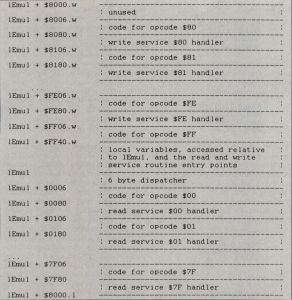
lEmul + $8000.w ----------------------------------------
                : unused                               :
lEmul + $8006.w ----------------------------------------
                : code for opcode $80                  :
lEmul + $8080.w ----------------------------------------
                : write service $80 handler            :
lEmul + $8106.w ----------------------------------------
                : code for opcode $81                  :
lEmul + $8180.w ----------------------------------------
                : write service $81 handler            :
                ----------------------------------------
     ...
lEmul + $FE06.w ----------------------------------------
                : code for opcode $FE                  :
lEmul + $FE80.w ----------------------------------------
                : write service $FE handler            :
lEmul + $FF06.w ----------------------------------------
                : code for opcode $FE                  :
lEmul + $FF40.w ----------------------------------------
                : local variables, accessed relative   :
                : to IEmul, and the read and write     :
                : service routine entry points         :
lEmul --------------------------------------------------
                : 6 byte dispatcher                    :
lEmul + $0006 ------------------------------------------
                : code for opcode $00                  :
lEmul + $0080 ------------------------------------------
                : read service $00 handler             :
lEmul + $0106 ------------------------------------------
                : code for opcode $01                  :
lEmul + $0180 ------------------------------------------
                : read service $01 handler             :
              ------------------------------------------
     ...
lEmul + $7F06 ------------------------------------------
                : code for opcode $7F                  :
lEmul + $7F80 ------------------------------------------
                : read service $7F handler             :
lEmul + $8000.1 ----------------------------------------
|
Figure 1 is a diagram of the memory organization of the emulator's code. This memory block can be anywhere in the ST's memory and need not be on a 64K boundary, since everything is relative. The pointer lEmvl points to the dispatcher, all memory references are relative to this value.
Read and write service handlers are another 256 routines I'll mention soon, but they were able to share memory with the 6502 dispatcher since none of the opcode routines was ever longer than about 80 bytes.
I discovered all this just a few weeks before the ST-Log containing the emulator hit the stands. Too late now, I thought, but it sure will make the next update look better.
Some of you may recall from the first emulator what the read and write service routines were all about. As the 6502 emulator is chugging along, every once in a while it will encounter a 6502 instruction that affects a hardware register or screen memory location. In the first Xformer, I had an extra 64K memory block that mapped each byte of the 6502's address space to a type of memory. $00 indicated it was normal RAM, and values from $01 to $FF were used to indicate various hardware registers. When the emulator came across a memory reference to a location whose type was not $00, it branched to a separate dispatcher which took the type byte ($01 to $FF) and did another jump table dispatch to a handler.
This worked fine to trap all write to screen memory and hardware registers, but reading bytes from screen memory also caused it to jump to this dispatcher. In Xformer II, I fixed this by having two separate 64K arrays: one for memory reads and one for memory writes. The read array contains 62K of zeroes and 2K of non-zero values which are mapped to the 2K of hardware register memory. Thus any reads from the screen memory, BASIC or OS ROMs are treated as normal reads from RAM.
Again, rather than use a jump table, I created two more six-byte dispatchers: one for the read handlers, one for the write handlers. Each one dispatches to a 64K block of memory, with the handlers at 256-byte intervals. To simplify things (and save a lot of memory), the two blocks were overlayed. Read handlers took one 32K chunk, and the write handlers took the other 32K. All this was offset by 128 bytes and overlayed on top of the 64K block of code used by the 6502 emulator. This now completes the diagram.
What made this whole thing tricky was that I was writing this using Megamax C, and then later Laser C. Neither one allows you to write code that spaces routines 256 bytes apart—unless you manually count the bytes yourself. So, using the old jump tables, the emulator constructs the 64K block at runtime. All the opcode handlers and read and write handlers are compiled without any sort of spacing, then at runtime, the routines are copied one by one into this 64K block, at 256-byte intervals. Again, since all the code is relative, there was no need to worry about absolute memory references getting messed up.
Smarter code
Xformer II runs at 40% of the speed of the original 8-bit OS, so some other speed increases must have been found, right? Yes!
The remaining speedups were basically just code optimizations. They required a less significant leap of the imagination than the self-modifying dispatcher but are interesting nevertheless because they once again show that the obvious code is not always the fastest. In fact, as you will see, there are many 68000 instructions that shouldn't even be allowed, because by using them, we all end up writing slower code. A quick look at any part of the ST's ROMs shows this.
One of the most common ones missed by most compiler writers is the method used to clean up the stack after a function call. The 68000 provides a way of doing the clean-up fast with the ADDQ (add quick) instruction, which, in two bytes of code and eight cycles, adds a number from 1 to 8 to an address register. This is fairly fast for most calls, but what happens if there were more than eight bytes on the stack? Flip the page in the Motorola book, and the obvious choice seems to be ADDA (add to address register), which requires an extra two-byte signed offset, and an extra four cycles. What most people miss is that the same thing can be accomplished with no speed loss with the LEA (load effective address) instruction. For example, to increment the stack pointer by 20, do a "lea 20(a7), a7" (eight cycles) instead of a "adda.w 20(a7), a7" (twelve cycles).
Another goodie that most people have caught on to is that to shift a register by one or two bits to the left, it is faster to add it to itself rather than shifting it. For example, use "add.w dO, d0" (four cycles) instead of "lsl.w #1, d0" (eight cycles). All the flags except overflow are affected the same.
Another common mistake is when clearing registers. To clear a data register, use "moveq #0, d0" (four cycles), instead of "clr.l d0" (eight cycles).
I ran across these mistakes in my own Xformer code, and by making these small changes, the code sped up by about another 10%.
This still leaves a considerable speed increase unaccounted for. A quick look through the Xformer II code would seem to indicate that it had reached its top level of optimization. The self-modifying dispatcher can't be improved upon, and any possible instruction substitutions had been made. Again, I turned to the tracing dispatcher for help.
I set it up to run some program, say Atari BASIC, for about two minutes. Then, two minutes and four million 6502 instructions later, it dumped a list of the number of times each of the 256 opcodes had been executed. Of course, the 100 or so NOPs all had counts of 0.
I found that most programs (like Atari BASIC), the operating system and most binary files only use a set of about 110 to 120 unique instructions out of the 150 or so possible. (The emulator does not handle or look for the "hidden" 6502 instructions). Of these, there is a core of about 30 instructions that are executed almost all the time. The remaining 90 or so are used very infrequently. Topping off the list of most executed instructions were BEQ and BNE, each with about 7% of the total count. Following them were instructions like LDA #, ADC #, LDY #, and STA zero page. As expected, the LDA, LDX, and LDY instructions, with all their addressing modes, were executed about half the time. The remaining half is taken up by store instructions like STA and the remaining branch instructions like JMP, JSR, RTS, BCC, etc.
This now made me focus on the LDA instructions. How could they be sped up? Listing 1 and 2 are examples of the old code that emulated the LDA abs instruction (opcode $AD) and the code that replaced it.
The first optimization deals with how a 16-bit effective address, in low-byte high-byte format, is loaded into a 68000 register. This particular function is required in many places in the emulator and is even required by the ST to read GEMDOS disks, which are in MS-DOS (low-byte hi-byte) format.
The most obvious code would be something like this:
move.b 1(a0), d0
lsl.w #8, d0
move.b (a0), d0
addq.l #2, a0
This requires 12 + 24 + 8 + 8 = 52 cycles on the ST. Ouch! In last year's article, I was patting myself on the back for coming up with the following code:
move.b 1(a0), -(sp)
move.w (sp) +, d0
move.w (a0), d0
addq.l #2, a0
This requires 16 + 8 + 8 + 8 = 40 cycles. It takes advantage of the fact that the 68000's stack pointer always decrements by 2, not 1. Thus putting the byte on the stack then reading a word has the effect of shifting it eight bits.
Better, but not optimal, as I was shown by another reader. I had overlooked the MOVEP instruction, which is almost (but not quite) suited for this purpose:
movep.w 1(a0), d0
move.b (a0), d0
addq.l #2, a0
This requires only 16 + 8 + 8 = 32 cycles. For those not familiar with MOVEP, it works like this: Rather than fetching two consecutive bytes from memory (which must be word aligned), it fetches a byte, skips a byte, and fetches another byte, with no alignment restrictions. It's handy for accessing some of the 8-bit devices mapped on the STs memory, like the video chip, which have registers spaced apart like that. The reason it is useful here is that it loads the high byte of the effective address straight into the high byte of D0.w, thus eliminating any need for shifting.
Going back to the code segment above, we now have the effective 16-bit address of the LDA instruction in the data register labeled drEA. In Xformer II, I immediately check that effective address against $C000. If the address is below $C000, it means we are fetching a byte from the 48K of RAM in the Atari 800, or maybe from the BASIC cartridge ROM. In either case, it is safe to do so. Otherwise the status byte is loaded and some service routine is executed.
In the old emulator, I had a single entry point to the service routine, so the flag isread was used to tell the service routine whether a read or write was being attempted. Although this is unnecessary in Xformer II which has a separate read and write handler, there is a better way of setting the isread flag.
This time the instruction that saves the day is, oddly enough, called ST (set true). It is one of sixteen set instructions that the 68000 supports. They are similar to branch instructions, except that instead of branching to the effective address, they simply set it to $00 or $FF. For example "st (a0)" is the same as saying "move.b *$FF, (a0)" but faster and shorter. I frequently used the ST and SF (set false) instructions in the Atari 800 graphics-emulation routines, where it is frequently required to clear or set a certain, bit plane.
Now we skip down to the actual loading of the accumulator, a "MOVE.B (arEA), drA" in both the old and new emulator. All that is required now is to update the 6502 status register, and we're done with the LDA opcode. In the old emulator, I simply read the 68000's status register, masked off the bits I needed, namely the zero and negative (Z and N) bits, and moved them to the data register drST, which kept track of all seven 6502 flags. As you can see, it required four instructions taking 12+ 8 + 8 + 4 = 32 cycles. The big speed hit is the fact that MOVEs to and from the status register take 12 cycles instead of the usual four required for MOVEs between data registers.
I spent several weeks thinking about this one problem. If some way could be found to eliminate the MOVE from the status register, maybe eight cycles could be saved. Once again, the tracing version of the emulator pointed out the solution.
Since most of the frequent opcodes were of the load variety (LDA, LDX, LDY), only the Z and N flags were getting updated frequently. The other flags, like carry and overflow, were updated after ADC, SBC, and shift instructions. I decided to reserve drST only for the N and Z flags, and keep the rest off-chip somewhere in memory where they could be accessed relative to the dispatcher.
This modification allowed me to MOVE the value being loaded directly into drST. The branch instructions, like BEQ, BNE, were then updated to simply test drST for a zero or non-zero value, rather than testing specific bits. This gave a significant speed increase, bringing the speed of the emulator up to the current 40%.
The actual implementation looked like this: drST was divided into three parts: the lower byte, the lower word and the whole register. The topmost bit (bit #31), was used to store the D (decimal) flag of the 6502, since it was rarely set or reset but checked constantly by the add and subtract instructions. It could be checked with a simple "TST.L drST." Similarly, the N flag was stored in bits 8 through 15, and could be tested for with a "TST.W drST." Finally, the zero flag could be tested with a "TST.B drST."
Each of the TST instructions takes only four cycles, rather than the eight required for a bit test. Fortunately, I did have a spare data register lying around, so I used it to store the carry flag. After some arithmetic operation, it could be set or reset with the SCS instruction, as could the overflow flag.
To see a great example of an instruction that really sped up, Listings 3 and 4 are the old and new code for the ADC# instruction. It assumes the decimal flag is off. Listings 5 and 6 are the old and new code for the ASL A instruction. Note the significant speed increases due to the better dispatcher and the better handling of flags.
A neat trick I use for setting the X (extended carry) flag in the status register without MOVEing to the SR for both the add and shift instructions is to simply add drC to itself. Since drC is updated with the "SCS drC" instruction, its value is always either $00 (carry flag clear) or $FF (carry flag set). Adding drC to itself will either generate $00 with no carry or $FE with a carry. The $FE is thrown out right away and is irrelevant, but it does accomplish the task in four cycles instead of 12.
Other Enhancements
Although the changes to the 6502 interpreter are the most important new features of Xformer II, there are other big improvements. Anyone who has used it will immediately notice the GEM-based interface which replaces the old text interface. Another enhancement is in the way disks are emulated. The old emulator cheated by monitoring the CIO entry point and branching off when disk operations were attempted. It was somewhat compatible at the file level, but did not allow for sector-level I/O and had no support for DOS disks.
Early in the development stages of Xformer II, I decided that a major key to compatibility was to be disk compatible. That would mean that someone could port an 8-bit, 5 ¼-inch disk to the ST (somehow) and run it on the emulator as if it was running on a real 8-bit computer.
Fortunately, the 8-bit disk has a simple format, similar to the format used by the ST itself. There are 40 tracks of 18 sectors, with 128 bytes in each sector. The sectors are numbered 1 through 720 and can be accessed by sending a SIO (serial input/output) command to the disk-drive controller. Because the controller is on the drive and not on the computer, it means that there is no way to bypass the controller (unless you stick in a Happy chip, but let's ignore this fact!). Therefore it was very simple to emulate the controller. It has a small number of commands, like format, read sector, write sector, and status. It also returns a very small number of error codes.
What I originally did to emulate the controller was to keep a 90K block of memory which contained the information of the 720 sectors. When a command was sent to the disk drive, the emulator would simply grab 128 bytes in this block and treat it as a sector. Writing a sector meant writing to this block, and reading a sector meant reading from this block.
This has worked so well that this method is still in the current emulator. Of course, the requirement of keeping these 90K blocks of memory (180K for double-density emulation) means that Xformer II can only run on a one-meg Atari ST, as some unhappy 520ST owners found out.
Another improvement is in the way I handle hardware registers. The old emulator handled a few locations, like the sound registers and color registers. This was done by assigning unique status bytes to those registers in the status array. Unfortunately, I left a lot of the registers untouched. Xformer II on the other hand at least does something, anything, when one of the 136 hardware locations (yep, 136, count 'em) in the ANTIC, POKEY, PIA and GTIA chips is accessed. Xformer II also supports multiple occurrences of hardware registers by masking unneeded bits from the effective address.
Player/Missile graphics are now finally supported, to a degree. After unsuccessfully trying to come up with fast pixel-blitting routines to do software sprites (in much the same way that the ST's mouse cursor is done), I decided to cheat and take advantage of bit planes. Since the emulator runs in low resolution, which provides four bit planes, I could get away with using three of the bit planes for the regular graphics display of up to eight colors and then use the fourth bit plane to store the Players and Missiles. This way, when a player moves, its bit image is moved only within the one bit plane, leaving the underlying graphics image intact. These enhancements don't really contribute to the overall speed of the emulator, although they do greatly improve compatibility. The disk emulation and Player/Missile graphics code is written in C, taking advantage of Laser C's ability to use both C and assembly-language source code.
What next?
I'll try not to make any guesses as to what sort of emulators will be around next year. I really put my foot in my mouth last year by saying that the old emulator was about as good as it was going to get. And, unlike last year, I already know that I'll be working on a new version of the emulator which should run at full speed or faster. It will simply compile the 6502 code into 68000 code and eliminate the need for a dispatcher all together. This alone can almost double the speed of the current emulator, but I've got a few other tricks up my sleeve which I'm not going to discuss quite yet.
I know that several other emulators are being written, one a 6809 emulator based on the technology I presented last year, and another 6502 emulator, so things are definitely going to get better yet!
Anyone interested in getting their hands on the source code to Xformer II can find it on DELPHI, CompuServe and GEnie. It's a huge ARC file, and you must have Laser C from Megamax if you want to compile it.
I can be reached by mail at the following addresses.
CompuServe: 73657,2714
DELPHI, GEnie and BIX: DAREKM
I for one am going to apply some of the tricks from the emulator and use them to write some fast replacement routines for TOS, which, as I already mentioned, uses the most non-optimal 68000 code almost everywhere.