ON DISK!
GFA Object
A 3D-Modeling Program For Use With GFA BASIC
BY ANDREW REESE
START EDITOR
In the January 1989 issue of START, we brought GFA BASIC 2.0 to the START disk and your response was overwhelming. This issue, we present GFA Object for use with color monitors. GFA Object lets you create three-dimensional objects that you can use in your own GFA BASIC programs. If you're at all interested in 3D, read on. . .
Into the third dimension with GFA Object. Files OBJECT.ARC and ANIMATOR.ARC on your START Disk!
Most of you are aware of the power of GFA BASIC. Version 2.0 of the Interpreter is the standard against which all BASICs for the ST are judged.
Because of the power of GFA BASIC, GFA Systemtechnik created a whole series of programs designed to work with it--and many were actually written in GFA BASIC itself. GFA Object, featured on this issue's START disk, is a good example. It not only shows just how capable GFA BASIC is as a language, it also is a powerful 3-D object creator in its own right. You can use it to create objects or images for use in your own GFA BASIC programs or as macro-data for use in GFA Draft Plus. As a bonus, you can use objects created in GFA Object with GFA Vector, the 3D animation program, coming to you soon on your START disk!
Getting Started
GFA Object is on your START disk in the file OBJECT.ARC along with six module files. (Modules are basic shapes--building blocks for more complex objects.) Copy OBJECT.ARC to a blank, formatted disk and un-ARC it, following the disk instructions located elsewhere in this issue. When you are finished, double-click on the OBJ_COLR.PRG icon to run the program. You will need an ST or Mega system with a color monitor to run GFA Object and must be in medium resolution.
Because it's impossible to reproduce the entire GFA Object manual in the pages of START, what follows is a quick overview with some basic information and a button-by-button and menu-by-menu explanation of the program's functions. However, just as we were able to do with GFA BASIC 2.0, we have obtained a limited number of copies of the original 150-page manual. If you would like to purchase one, see the instructions at the end of this article.
When GFA Object loads, you will see the editing screen shown in Figure 1. This is the screen in which you will create and edit your objects. The main window (the Edit Field) shows the Front View of any object, while the two small Help Screens to the right show the Right and Top Views (and are labeled, appropriately, as "From Right" and "From Top"). The menu bar at the top of the screen includes Desk, File, Edit, Object, Mod+Block and Options headings. Below the two Help Screens are the Z-scroller, the coordinates box and the status box.
Diving In
If you are familiar with CAD-3D and Cyber Sculpt from Antic Software, you may be a bit disorientated in the GFA Object universe at first. In GFA Object, the Y-axis runs vertically in the front view, the X-axis horizontally and the Z-axis represents depth. In the Edit Field, the origin (0,0 point) in the X and Y dimensions is in the lower left-hand corner of the window and the dimensions of the universe are approximately 42,000 units (pixels) in all directions.
When you enter GFA Object, you will be in Point mode, as indicated in the status box. In this mode, you can place points anywhere in the Edit Field. To create edges, you will need to select the Edge mode from the Edit Menu In the Edge mode, you can create edges by first left-clicking once in the Edit Field. When you do so, you will see a question mark appear in the status box. This indicates that you have not finished an edge. When you left-click a second time in the Edit Field, you will see an edge line appear between the two points. As long as you are at the same Z-location as an edge, it will appear as a solid line; move away from that Z-location and it will appear as a doted line
To create a surface, select Surface mode from the Edit window and place up to 20 points in the Edit Field; as long as you have not finished a face, two question marks will appear in the status box. You must finish a surface by left-clicking on the first point you set. You may find it difficult to find the precise location of that first point; if you do, move the cross-hairs near the point and then right-click. The cross-hairs will move to the closest point; if it's the first point you set, left-click and you will complete a surface.
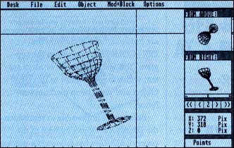 |
| Figure 1. GFA Object's Edit Field, in which you create and modify your objects. All functions are selected from the extensive drop- down menus for easy operation. |
If you try out making a few edges, you will notice in the help screens that they are all in the same plane, i.e at the same Z-location. You may use the Z-scroller to change the Z-location. Click on the double arrows to change it rapidly or the single arrows to change it more gradually. If you want to change the Z-location quickly to that of one of the points in the Edit Field, left-click on the "Z" in the center of the Z-scroller. The cursor will change to an open cross-hairs. Place the cursor over the point whose Z-location you wish to use and left-click. The Z-location will immediately change to that of the point.
Alternatively, you may left-click on the Z location in the Coordinates box. The Z-location will disappear and you may then type in a new Z-location. Finally, you may use the sliders on either of the help screens to move the Z-location roughly. To move them, you must click and hold the left mouse button on the slider "handle." You can then drag it in the direction you want.
NOTE: Unlike CAD-3D and Cyber Sculpt, creating a series of connected edges does not create a surface. You must use the Surface mode to create a surface that will be shaded in the Display mode.
Coming Up For Air
Take a few minutes to play with the program. You can create surprisingly complex objects through the simple techniques you've already learned. Don't worry if you make mistakes. You can't hurt your computer by making a Frankenstein's monster of a mess in the Edit Field. When you're done playing, select New object from the File Menu. When you click on the Yes box in the confirming dialog box, all your mess will be gone. Let's run down the menus now.
The Desk Menu
- GFA-OBJECT Info--Displays the program information and a fascinating little drawing routine.
- Desk Accessories--Any desk accessories you have installed can be accessed from the Desk Menu.
The File Menu
- Load Object--Lets you load an object from saved in GFA Object format. A bit of explanation of the nomenclature is needed here. You will see the term "module" used in the Menus; any object can be treated as a module and vice versa. Modules are intended to be small "building blocks" (in CAD-3D, they're called primitives), from which you create more complex objects. You may load any of the modules that came on your START disk directly into the Edit Field by using the Load Object option.
- Save Object--Saves your current object to disk with the filename extender .OBJ.
- Load as ASCII--Loads an object from disk in ASCII file format. The full file format is explained in Chapter 7.2 of the GFA Object manual.
- Save as ASCII--Saves your current object to disk in ASCII file format.
- Load picture--Lets you load a .PI2 DEGAS (or Doodle) format picture file. You must be in Display Mode first to see it, however GFA Object uses the current color palette for any picture you load. You will need to have the Control Panel loaded as a desk accessory to change the palette to suit the picture you load.
- Save picture--Lets you save the current screen as a DEGAS.PI2 (or Doodle) format picture.
- Delete File--Lets you make room on your disk by deleting a file.
- Drive--Lets you select the current disk drive that GFA Object will look to for files.
- Memory--Displays the number of points, edges and surfaces you have used, the number still available, the amount of free memory available and the amount of free disk space.
- New Object--Clears the Edit Field of all objects.
- Quit--Exits GFA Object.
The Edit Menu
- Edit mode--Selects the Edit field for creating and modifying objects. Occasionally, when switching from Display mode to Edit mode, the large cross-hairs will "print" on the screen, creating unwanted lines. Simply re-select Edit mode and the Edit Field will be re-drawn and the lines removed.
- Display mode--Selects the Display screen for displaying objects. See Figure 2.
- Point mode--Selects Point mode for placing points in the Edit field.
- Edge mode--Selects Edge mode for placing edges in the Edit field.
- Polyline mode--Selects Polyline mode for placing a polyline in the Edit field. A polyline is a series of up to 20 points continuously connected by edges. Remember: a polyline--or any other edge--does not define a surface that will appear solid in Display mode with Hidden line active.
- Surface mode--Selects Surface mode for placing surfaces in the Edit field.
- Delete mode--Selects Delete mode to remove points from the Edit Field. To remove a point, select Delete mode and then click in the Yes box in the confirming dialog box. The letters "De" will appear in the status box. Move the cursor near the point you want to delete (you may have to move the Z-location so that it is the same as the point), right-click to move the cross-hairs onto the point and then left-click to delete the point. NOTE: Deleting a point will also delete all edges connected to it. To exit Delete mode, re-select it from the Edit Menu and click in the No box in the dialog box.
- Displace points--Lets you move a point in any dimension. To displace a point, select Displace points, then type in the amount of displacement you want in the dialog box; pressing the Return key indicates no change when you have entered the values, the dialog box will disappear and the cursor will change to an open crosshairs. Place it near the point you want to displace and left-click. The point will be displaced according to your instructions. You will remain in Displace point mode until you right-click to exit.
- Point size--Lets you choose the size of the points already placed in the Edit Field. Default is 1-by-1 pixel, but you can change this to 3-by-3. Points added after this change will appear as small crosses in the Edit Field.
- Blend in numbers--Lets you add in numbers that identify the point numbers, the edge numbers or both to aid you in defining an object. This is especially useful when defining an object by entering data manually (see below).
- Smooth out data--Converts all fractional point definition data to integer data. This will, however, prevent use of the slow mode of displaying Hidden-Line objects (see below).
- Enter data--Lets you define points, edges or surfaces by entering numerical location data manually.
- Display data--Displays the location data on the screen for the current object.
- Print data--Prints the location data on your printer for the current object.
The Object Menu
- Rotate object--Lets you enter values (in degrees) to rotate the object in the Edit Field.
- Displace object--Lets you enter values (in pixels or the currently defined unit of measurement) to move (displace) the entire current object in the Edit Field.
- Change object size--Lets you change the size of the current object. Values of less than one reduce the size of the object in that dimension, while values of greater than one increase its size.
- Hidden-Line--Lets you select one of three modes for displaying objects in the Display screen: No hidden lines, quick and approximate or slow and exact.
- Central projection--Lets you select whether to display your object in parallel projection or with a vanishing point (central projection), to give a sense of perspective to the observor. Selecting central projection (and confirming its choice) actually changes the shape of the object. If you don't want to do this permanently, copy the object into the object buffer before selecting Central projection.
- Vanishing point--Lets you select a vanishing point for central projection. The default is in the center of the screen and 1,000 pixels deep.
- Centre of rotation--Lets you choose between the default center of rotation (the center of "gravity," or computed center of mass of the object) and an arbitrary center of rotation that you can select.
- Light source--Lets you choose the location of the light source used to shade objects in the Display screen. Default is X=1, Y=1, Z=1, placing the light to the left, below and to the front of the object. Values of X=-1, Y=-1, Z=-1 places the light to the right, above and to the rear of the object.
The Mod+Block Menu
- Load module--Lets you load a module (an object) into a special buffer so that you can use it to create complex objects.
- Show module--Lets you display the module in the main window to insure that the module is the one you want.
- Merge module--Lets you move the module into the Edit Field and merge it with the current object. Step-by-step instructions will appear in the upper right-hand corner of the screen to guide you through this.
- Object buffer--Lets you store the current object in a temporary buffer.
- Change over--Lets you swap the contents of the object buffer with the object in the Edit Field.
- Mark block--Just as in word processing, Mark block lets you select all or a portion of the current object for later manipulation. Again, step-by-step instructions will appear in the upper right-hand corner of the screen to guide you through this.
- Show block--Once you have marked a block, it will be shown by heavy, black points. If you then change the Z-location, the block will no longer be shown. Show block restores the heavy marks so that you can see what you've marked.
- Block as module--Lets you place a block in the module buffer, so that you can "copy" portions of an object back onto that object repeatedly. Placing a block in the module buffer will replace whatever is already in the module buffer.
- Rotate block--Lets you enter rotation values (in degrees) to rotate a marked block.
- Displace block--Lets you displace (move) a marked block, by entering values (in pixels or the current unit of measurement).
- Change block size--Lets you change the size of a marked block, similar to changing the size of an object.
- Delete block--Lets you delete a marked block, along with all edges running to points in the block.
The Options Menu
- Set units of measure--Lets you name and define an alternate unit of measurement, instead of the pixel used as a default. The new unit of measurement can be anywhere between 10 and 100 pixels in length.
- Blend in scale--Displays a scale along the bottom and left edges of the Edit Field. It is on by default.
- Blend in grid--Toggles a grid on and off in the Edit Field to aid you in locating components of an object.
- Help windows--Whenever you make a change in the object or the Z-location of the Edit Field, the Help windows are redrawn along with the Edit Field. If you find that the time that this takes is burdensome, you may switch off the Help windows by selecting this option. To restore them, reselect this option.
- Rotate profile--Similar to Spin in CAD-3D and Cyber Sculpt, this option lets you define a profile and rotate it around a center axis to create an object. This operation is like using a lathe to turn wood or metal. If you have an object in the Edit Field with fewer than 50 points, you may use it as the rotation template. In any case, creating a rotated object will replace whatever is in the Edit Field. Be sure to save or buffer any object you wish to keep before rotating a profile. The screen for the Rotate profile function is self-explanatory; experiment with this function to get a feel what it can do. Just remember that when you are satisfied with the settings, click on the Rotation-parameter OK box to reach the Edit Field for the Rotate profile function and when you have placed all of your desired points for the profile, right-click to create the object.
- Translate profile--Similar to the extrude function, this option lets you "squeeze out" an object, like toothpaste from a tube. You define the shape of the opening of the tube with 20 or fewer points, tell the program how many sections you want to squeeze out and how far apart they should be. Operation of the Translate profile function is quite similar to that of the Rotate profile function; switch the various settings by left-clicking on them and then click on the Translate-parameter ok box to reach the translate profile edit field. After defining the profile by left-clicking to set up to 20 points, right-click to create the object. Again, this will replace any object in the Edit Field.
- Pic background--In Display mode, lets you load in a DEGAS .PI2 (or Doodle) image to use as a background for your object. (If you have selected background in the Hidden-Line dialog boxes, you won't see your picture. Be sure that you say "no" to background if you want to load in a picture.
- GFA-DRAFT plus \.MAC--Lets you save a two-dimensional projection of an object as macro-data for use in the GFA Draft Plus CADD program.
- GFA BASIC \.GET--Lets you cut part of the Display screen and save it as a GFA BASIC Get file. You can then use the PUT command to load it into your program.
- Printer--Lets you choose drivers for 9- or 24-pin printers and print out an image of the screen.
Extras
We've also included on your START disk an animator program that does two things: First, it lets you convert your GFA Object .OBJ files into .DAT vector files so that you can load them into GFA Vector and GFA BASIC as objects. Second, it lets you experiment with animation of any object with fewer than 1,024 points. Now, you can get a feel for how your object will look in motion.
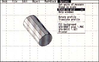 |
| Figure 2. You can choose a number of options for the Display screen. For example, you can choose to hide the lines at the back of an object, set a vanishing point and apply perspective and define the location of the light source. |
The Animator program is called ANIMATOR.PRG; you will also need to have ANIMATOR.CHN in the same directory to run Animator. These two files are contained in a separate ARC file named ANIMATOR.ARC. To use Animator, un-ARC ANIMATOR.ARC following the Disk Instructions located elsewhere in this issue and then double-click on ANIMATOR.PRG in either medium (color) or high (monochrome) resolution.
Also, on an upcoming START disk, we will present a file converter program to convert GFA Object files to CAD-3D format and vice-versa. Watch for it!
Finally, we have available a limited number of the original 150-page manuals for GFA Object. The price for the manual is $12.95, plus $3.50 shipping and handling. For VISA and MasterCard orders, simply call the Disk Desk toll-free at (800) 234-7001 and ask for #TH0002 or send your check or money order in the amount of $16.45 to: GFA Object Book Offer, 544 Second Street, San Francisco, CA 94107. Remember, the number of manuals is limited, so act fast!
If you would like to buy the original GFA Object manual, see page 54 for details.