
Three-Dimensional
Modeling for
Everyone
3D modeling on your ST in the file CAD_3D.ARC on Side 1 of your START disk.
PROGRAM BY TOM HUDSON
ARTICLE BY ANDREW REESE,
START GRAPHICS EDITOR
When Antic Publishing first brought out CAD-3D 1.0 in 1986, few people realized what Tom Hudson had created. It was a major breakthrough in ST graphics. Later on, Tom revised the interface and added a number of features in Version 2.0 and added Cyber Control to the 3D modelers arsenal. But it all started here. If you've ever been tempted to try 3D, here's your chance. CAD-3D 1.0 runs in color or monochrome on any ST.
If you have an ST, you've heard of CAD-3D. Over nearly four years, Tom Hudson's tour-deforce 3D modeling program has been one of the programs that "made" the ST. It was a pioneering program - everyone said that you just couldn't do 3D modeling on a microcomputer. Tom proved them wrong and the results of his efforts are on your START disk this issue.
Getting Started
To run CAD-3D 1.0, boot this month's START disk; the START Menu runs
automatically. At the main screen, click on Prepare, then select "CAD3D
version 1.0." The program and its accompanying resource file will unARC
directly onto the destination disk you specify. Four sample files are included..
A companion program, which animates 3D objects, is available. At the main screen, click on Prepare, then select "CAD-3D Animator." The program, ANIMATE.PRG, its resource file and two sample animations will un-ARC directly onto the destination disk you specify.
CAD-3D 1.0 will run on any ST, from a 520ST on up, and on either a color or monochrome system. If you have a 520ST, be careful about using Accessories or terminate-and-stay-resident (TSR) programs with CAD-3D 1.0; they may take up too much memory for CAD-3D 1.0 to run. CAD3D.PRG and CAD3D.RSC must be in the same directory. Double-click on CAD3D.PRG to run the program. You must be in medium resolution on a color monitor. It also runs on a monochrome monitor.
The CAD-3D World
The CAD-3D 1.0 Universe is an invisible cube into which you can look
from any direction. Three of the windows show views from the Top or Bottom,
Left or Right and Front or Back of this Universe. The fourth window, in
the upper-left corner of the screen, is the Camera window. You can move
this viewpoint around the Universe and create different perspectives of
your objects.
Each of the windows has slider bars along the right and bottom edges, a status line at the top, a full-screen button in the top-right corner and a toggle button in the top left where you normally find the close window button. Like all true GEM applications, only one window can be active at a time; the active window is the one with the sliders and buttons. Each time you make a change with a slider, click within the active window to update the display to reflect your change.
CAD-3D 1.0 uses drop-down menus for its functions and dialog and alert boxes for further input or information. These menus are the heart of CAD-3D 1.0. From the left, they are the Desk, File, Modes, Views, Light, Generate, Join and Objects menus. We'll go through each of them; as we do, you'll get a good idea not only of how to use CAD-3D 1.0, hut also how they interact.
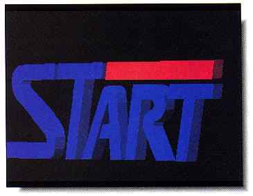
One of the sample files
included on your START disk is this
familiar logo (START.3D).
Load it up and experiment with
different perspectives
and camera angles, click on Solid
under the Modes menu,
then click on Super View to see
the image in colorful
3D.
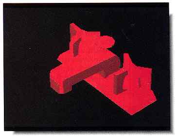
This faucet assembly
(FAUCET.3D on your START disk)
was composed of over
a dozen individual objects, many
of which were joined
into single objects. The parts were
created with both the
Spin and Extrude tools.
The Desk Menu
From the Desk Menu, you can select About CAD-3D to see the copyright
and credits notice or access any desk accessories you may have installed.
CAD-3D is a very robust application and exhibits few conflicts with well-behaved
desk accessories or TSRs.
The File Menu
At the top of the File Menu is New. Click on New to delete all
objects from the CAD-3D Universe and reset all settings. Because this is
a fairly drastic operation, you will he warned with an alert box and given
a chance to change your mind.
Next down on the File Menu is Load.... Click on Load.., to load in a new CAD-3D object file. Note that this performs a New first, so any objects you have in the Universe will be removed. CAD-3D 1.0 loads objects saved with the filename extender .3D, but can't load objects saved from CAD-3D 2.0 (or any other program) in the .3D2 format.
If you have any objects in the CAD-3D Universe, you can save them to a disk with Save All. This will save all objects in the Universe, whether they are Selected (visible) or not. If you only want to save some of your objects, but not all of them, create a Group by choosing which you want using Select from the Objects Menu, then use Save Group CAD-3D will automatically append the filename extender .3D, so that you don't have to do so.
Merge... adds the objects in a file to the objects already in the CAD-3D Universe without erasing any already there. If there is a conflict between the names of objects already in memory and those in the file, CAD-3D 1.0 will alert you and give you a chance to change the name of the conflicting incoming object.
Printout will produce a hard copy listing on your printer of all objects in the CAD-3D Universe. Your printer must be connected and on line.
Save pic saves any picture you have generated using Super view from the View Menu. A Super view is a full-screen low resolution image of your object. It will be generated in whatever mode you have selected in the Modes Menu: Wireframe, Hidden, Solid or Outlined and All Lines or Edges. You may save a Super view picture in DEGAS (.PI1 in color or .P13 in monochrome). NEOchrome (.NEO) or C.O.L.R. Object Editor format, selected by those entries on the File Menu.
Start ANI starts an animation file on disk that you can play back later with the ANIMATE.PRG proram. When the file selector box appears, enter a filename and click on OK. An animation can have any filename and extender, but color animations can't be played on monochrome systems, nor vice versa. Be sure you have selected the proper color pallete and object groups before you start an animation; you can't change them in the middle, although you can change lighting and camera and object positions.
Record turns your current camera view into a Super view and records it to disk as a part of your animation. After you have started your animation, make whatever changes you want in object position or camera position for the next frame and click on Record. Continue to make changes for each frame, clicking on Record each time; then when you've finished, click on Stop ANI. CAD-3D 1.0 will close the disk file and your animation will be complete.
special animation
player program
written for CAD-3D
animations.
The next three entries on the File menu are the choices for a saved Super view: DEGAS, C.O.L.R. or NEO. The active selection will have a checkmark beside it.
Quit will exit from CAD-3D 1.0. All objects and settings will be lost and you will be warned before this happens.
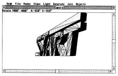
This is CAD-3D's Camera
box with the START image in Outline
mode. For dramatic effects
increase the Perspective value to
1000 then rotate left
30 degrees and down 10 degrees.
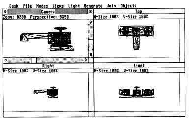
This is the CAD-3D 1.0
work screen, displaying the CAD-3D
"universe" with the faucet
assembly in the four different
windows. For a drain's-eye
view, add a little light from the
bottom center, and rotate
down 60 degrees and left 90 degrees.
The Modes Menu
At the top of the Modes Menu are the four choices for display of your
objects, both in the four windows and in the Super view. Wireframe
shows just the edges of the object and not the surfaces. (If you have also
chosen All lines at the bottom of the Modes Menu, the construction
lines CAD-3D 1.0 uses to construct faces will also be visible). Hidden
shows the object as a Wireframe, but removes all of the lines that would
not be visible because they're hidden by the front of the object. Solid
generates the faces of the objects and shades them according to the colors
and lights set. Outlined is just like Solid, except that it adds
the wire-frame outlines to the faces.
On a color monitor, Set Color lets you change the color of an object. If you have chosen 7 shades, you can choose among Red, Green, Blue, Yellow, Violet, Cyan or White for either of two different object colors. If you choose 14 shades, CAD-3D will have more shades to assign to an object's faces, but only one color of object can be in memory.
If you are on a monochrome system, you can't change the color of objects, but you can change the color of the background. White BK. selects a white background, while Black BK. selects a black background.
All lines was discussed above; Edges only will display
only the lines that form the edges of objects, not the construction lines.
| Cad-3D uses keyboard shortcuts to make your 3D-modeling easy. Here is a list of them: | |
|
On the Main Screen |
|
| W | Wireframe |
| H | Hidden |
| S | Solid |
| O | Outline |
| C | Set Colors |
| T | Top View |
| B | Bottom View |
| R | Right View |
| L | Left View |
| F | Front View |
| K | bacK View |
| I | Info |
| ? | About CAD-3D |
| Alt-N | New |
| Alt-L | Load |
| Alt-S | Save |
| Alt-M | Merge |
| Alt-Q | Quit |
| Alt-P | sPin |
| Alt-X | eXtrude |
| Alt-E | sElect |
| Alt-D | Delete |
| Alt-H | Home |
| Alt-O | rOtate |
| Alt-R | Record animation frame |
| Alt-C | resCale |
| Alt-Z | redefine color |
| Arrows | After slider settings by one unit |
| Shift-Arrows | After slider settings by ten units |
| Esc | Like toggle button in active window |
| Backspace | Full screen |
| 1,2,3,4 | Activates Camera, Top-Bottom, Left-Right or Front-Back window, respectively |
|
On the Spin and Extrude Tool Screens |
|
| Alt-C | Connect toggle (in Spin) |
| Alt-B | rubberBand toggle |
| Alt-D | Do function |
| Alt-G | Grid toggle |
| Alt-S | Snap Toggle |
| Alt-A | Abort |
| Alt-R | Reset |
| Undo | Remove active point |
| ? | About... |
| Esc | Abort |
The Views Menu
The top six entries on the Views Menu choose which three of the six
possible views will be shown in the Auxiliary windows. Those selected will
have checkmarks beside them.
Updates lets you choose which windows will be automatically updated every time you make a change to the object. The fewer windows that update, the faster will be the overall operation. Windows that aren't set to automatic update will be grayed out. To select which windows are automatically updated, click on Updates, then select the windows from the dialog box. Windows that will update are shown in inverse.
which you can look from any direction.
Super view generates a Super view image of your objects. To exit from Super view, click a mouse button. If you have generated a Super view during a session in CAD-3D, you can look at it with Look.
The Light Menu
There are three possible lights, LightA, LiglitB and
LightC in CAD-3D 1.0 plus Ambient, or overall, light. On
the Light Menu, you can turn these lights on or off and set their locations
and brightness. To turn a light on or off, hold down the [Shift] key and
click on the Light Menu entry for the light you want to switch. Lights
that are on will have a check-mark by their menu entries. Ambient light
can not be turned off with a [Shift]-click; you have to set its brightness
to 0.
When you click on a Light Menu entry, it brings up the Light-source definition box. Across the top are eight light levels from 0 through 7. To set a light's brightness, click in the numbered box representing the brightness you want. To set the location of the light, click on any combination of the location boxes in the middle. When you're satisfied, click on OK or click on Cancel if you want to leave the light the way it was. CAD-3D lights are omni-directional lights, not spotlights, and shine uniformly in all directions.
The Generate Menu
On the Generate Menu are the tools you use to generate objects. At
the top are Spin and Extrude, which take you into the Spin
Tool and the Extrude Tool, respectively. Below that are the primitives,
Sphere 1, Sphere 2, Sphere 3, Torus, Cube
and Wedge. Click on any of these to generate that object. You will
be given a chance to set the color, shade and name of the object before
it's generated. The spheres differ only in their complexity with Sphere
3 being the most complex - and smoothest.
The Spheres and the Torus (a doughnut-shaped object) are generated with the Spin Tool. After you've generated one of these objects, enter the Spin Tool and you'll see the template used to generate the object. Similarly, the Cube and Wedge are generated by the Extrude Tool; take a look in the Extrude Tool after generating one to see the template.
The Spin Tool and Extrude Tool use similar screen lay-outs, but there the similarities end. The Spin Tool is like a lathe that creates a circular "spun" object from a pattern. The extrude tool is similar to the shape of the end of a toothpaste tube. When you squeeze the tube, the toothpaste takes the shape of the end of the tube. In the Extrude Tool, you set the shape of the "toothpaste nozzle."
Two rules in the Spin and Extrude Tools: always place points in a clockwise direction and in the Spin Tool, place points only in the right side of the screen - CAD-3D will mirror your points on the left side.
On their Options Menus, both tools have a Grid to help you align points and a Snap that only lets you place points at the Grid points. Also, both tools have an Abort that lets you exit the tool without creating any objects. Both tools have an Edit Menu with options to Reset (clear all points), Remove (to delete the current point) and Rubberband - stretchy lines that show you where lines would lie as you move the mouse.
Connect in the Spin Tool lets you connect up the first and last points to create a closed object.
The current point is shown with a crosshair. You can move the crosshair to different points for editing by clicking in the vertical slider bar at the right of the screen. The sliders along the bottom of the tools control the number of segments generated in the object. Try different settings to see the effects.
The Join Menu
On the Join Menu are just two options: Do Join and Info.
Do Join is used to combine two separate objects in several different ways.
You can Join objects that are not touching, just to combine them under
a single object name or you can join overlapping objects, If objects do
overlap, you can Add them together, removing the parts where they overlap
or Subtract one from the other, removing not only the second object, but
also those portions of the first where they overlapped. A third alternative
is to Stamp the shape of the second object on the surface of the first.
Finally, you can use the And function, which will create a third object
that consists of only the parts of the two objects that overlap.
When you click on Do Join, you'll be taken to the Object Join Control panel. Across the top are the names of the objects in the universe. Below that is an "equation" and below that is a set of buttons. Click on the names of the objects you want to join and they will appear in the equation.
Click on the button for the operation you want and the appropriate symbol will appear in the equation. Enter a name for the resulting object and click on OK. CAD-3D will then perform the Join if it can. Some Joins are impossible for it to handle and Joins of complex objects can be time-consuming.
The most important thing to remember about Joins is that the two original objects are deleted from the universe; make sure you have duplicates saved to disk if you want to keep them.
to try 3D!
The Info option lets you see statistics on the objects in the universe and their totals. At the top are the object number and its name. Below them are the statistics for that particular object. Below that are the statistics for all the objects in the universe, showing the maximum number you can have for your memory and the number you have available for additional objects. cycle through your objects by clicking on Next.
The Objects Menu
At the top of the Objects Menu are the Select and Delete options. When
you click on one of these you will bring up a selection box to choose the
objects that will be visible (Select) or removed from the universe (Delete).
Click on the names of the objects you want to affect and then on OK; any
Delete operation will bring up an alert box to caution you that once an
object's removed, it's gone for good.
microcomputer?
They said it couldn't
be done.
Select is good to use when you want to work on just a part of your scene and get the other objects out of the way, or when you want to scale or move some of your objects, but not all.
Next down are Drag one and Drag all. These are alternatives -only one can be active, indicated by a checkmark. They affect whether a Drag operation operates on a single object or all of the Selected objects in the universe. To Drag an object or group in one of the Auxiliary windows, place the mouse cursor on the object and press and hold down the left mouse button. A surround box will appear. While still holding down the mouse button, Drag the box where you want the object(s).
Omni Drag, Vertical and Horizontal are also alternatives. If you want to Drag an object or group, you can limit how you drag it by selecting one of these options. Omni Drag lets you Drag objects in any direction, while Horizontal limits movement to the horizontal direction and Vertical to the vertical direction. This may be important if you're looking to align objects precisely.
Home moves all selected objects in the center of the universe in all three directions.
Universe and Group are two more alternatives. When you want to Scale or Rotate an object or objects, you have two choices - use the center of the group (Group) or the center of the universe (Universe) as the point around which the action takes place.
Rotate calls the Object Group Rotate box. It lets you rotate the selected objects in the active Auxiliary view window around one axis. The Object Group Rotate box uses a pie chart to show the angle of rotation. To set the rotation, use the slider; clicking in the gray area will change the rotation ten degrees, while each arrow button at the ends of the slider changes the rotation by one degree.
You can Rotate an object up to 180 degrees in either direction in a single operation. When the angle of rotation is what you want, click on OK.
Scale calls the Object Group Size box that lets you Scale objects or groups up or down in all three dimensions at once. Like the Object Group Rotate box, it uses a slider. You can halve (50%) or double (100%) the object size in a single operation.
You can also Rotate or Scale an object in one or two directions in another way. Along the edges of the active Auxiliary are two sliders and in the upper left corner is what appears to be a close window button. This button toggles between Rotation and Scaling. Whichever function is active will be shown in the status bar. Use the slider bars to adjust the function, then click in the window to activate it. You can adjust both sliders and then do the operation with a single click in the window. The changes you make in the sliders will be reflected in the status bar so that you can set the operation accurately.
Reshade lets you redefine an object's color and/or shade at any time. Just click on Next to find the object you want to change and select the color and shade you want. The shade you set from 0 to 7 will be the brightest shade on the object; the lower the shade, the darker will be the object.
The CAD-3D Animator
ANIMATE.PRG is a special animation player program written for CAD-3D
animations. Its functions are all menu-selected and quite straight-forward.
You must start Animator on a color system in medium resolution, even though
the animations are in low resolution. ANIMATE.RSC must be in the same folder
as ANIMATE.PRG.
On the File Menu, Load lets you load animations you've created in CAD-3D; remember that monochrome animations can't be loaded into a color system, and vice versa. Quit exits Animator and returns you to the desktop.
On the Option Menu, White BK. and Black BK. are alternatives for monochrome users only and let you set whether you want a white or black background for your animations.
The Animate Menu lets you start your animation playing (Animate!), set it to play continuously (Loop) or play through only once (Stop). To stop an animation while its playing, press any key.
Tom Hudson has long been thought of as the ST Guru of Graphics.
His credits include DEGAS; DEGAS Elite, CAD-3D, Cyber Control, Cyber VCR
and Creation! Tom lives in Kansas and is an independent software developer.
Andrew Reese was formerly Editor of START and is now START's Graphics Editor
and a product manager for a San Francisco Bay Area graphics software company.
| CAD-3D 2.0 Upgrade Information
The best got better! To upgrade CAD-3D v. 1.0 to v. 2.0, send your original March 1990 START disk (not a copy), your name, address and daytime phone number along with a check or money order for $65 (plus $3.50 S/H) to CAD-3D Upgrade, Antic Software, 544 Second Street, San Francisco, CA 94107. |