THE 410 HI-REL MOD
Eliminate the most frequent cause of bad loads
In the April 1983 issue of ANTIC, I described a "High-Reliability Modification" (hi-rel mod) for the Atari 410 cassette recorder. Unfortunately, many of you missed that particular issue and I've received numerous requests for reprints. In this month's column I'll go back over it in detail. My first mention of the hi-rel mod was simply an aside in a column devoted to the 410 recorder's digital-playback circuits. This time I'll concentrate on the mod itself.
A BRIEF DECRIPTION
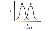
First, I'll briefly describe the hi-rel mod and why it works. The 410 and 1010 cassette recorders use two parallel filter circuits that convert the signal recorded on a program cassette into a form the Atari computer can understand. Think of these two filters as a couple of bellshaped curves, like those shown in Figure 1. Any signal that falls in the band (window) of the low filter is converted into a logical "zero"; a signal that falls into the window of the high filter is converted into a logical "one." Any signal that falls outside the windows of both filters is ignored.
SPURIOUS SIGNALS
Unfortunately, electronlcs, like life, is not a simple matter of black and white. Due to a number of different causes, spurious signals can get through the filters and cause a bad CLOAD. There is no way to eliminate all of these bad signals, but a careful study of the Atari recorder's digital playback circuits can provide us with a way to eliminate the most frequent cause of bad loads.
Bad loads are often caused by what might be called "cross-talk" between the two filters. Look again at the curves in Figure 1. You'll notice that they overlap somewhat. As a result, it's possible for the circuit to receive a valid signal but assign the wrong value to it. Thus, what should have been a zero becomes a one or vice versa. The result of this mixup is a bad load.
POSSIBLE SOLUTIONS
Two possible solutions immediately come to mind. First, we could add a new circuit that would blank out the region of overlap. This solution involves the addition of a "notch-filter" to the circuit. Such a circuit modifcation would be extremely effective, but it would also require the use of an oscilloscope to properly tune the notch-filter. There has to be an easier way than this to achieve our goal. Let's look at the second solution.
The second solution is to narrow the skirts of two filters so that the region of overlap is minimized. This can be accomplished by replacing a single resistor in the feedback loop of each filter. All that's needed is a soldering iron and a screwdriver. This seems to be the best solution we can come up with without spending a small fortune on an oscilloscope.
REPLACING THE RESISTORS
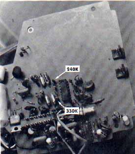
First, let's take a look at the two resistors we need to replace. They're highlighted in Figure 2. One of them is a 240K-ohm resistor; the other is a 330K-ohm resistor. Their power ratings are not critical.
Please keep in mind that Figure 2 is a photograph of my recorder - your recorder may have a very different layout. The resistors in my 410 are ten-percent resistors, but some of the newer recorders contain five-percent resistors instead. To significantly narrow the skirts of the bell curves, we need to use one- or two-percent resistors.
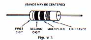
Some of you may not know how to "read" a resistor. Look at Figure 3. It shows a side view of a typical resistor. Notice the bands on its side. These are color-coded according to an industry standard that is used to label every resistor. The first band identifies the first digit of a two-digit value. The second band identifies the second digit. The third band shows how many zeros should be added at the end of the two- digit value. For example, on a 24000 (240K) resistor a red band(2) is followed by a yellow band(4), which is followed by another yellow band (X100000). Because of this standardized coding system, our two resistors can be identified by the following patterns:
240K.. RED/YELLOW/YELLOW
330K.. ORANGE/ORANGE/YELLOW
The fourth color band on a resistor is used to show the "tolerance" of the resistor. The specific codes are:
GOLD......5%
SILVER..10%
GOLD.......20%
The color codes for the first two bands are:
BLACK------ 0
BROWN------1
RED-----------2
ORANGE----3
YELLOW----4
GREEN-------5
BLUE---------6
VIOLE------- 7
GRAY ------- 8
WHITE------ 9
The color codes for the third band are:
BLACK------ X1-
BROWN------X10
RED-----------X100
ORANGE-----X1000
YELLOW------X10000
GREEN-------X100000
BLUE---------X1000000
VIOLE------- X10000000
GRAY ------- X100000000
WHITE------- X1000000000
WHAT IS A ONE-PERCENT RESISTOR
Now I'll explain what I mean by a one-percent resistor -- the answer is not what you might think. The easiest way to explain the term is to use an example. Let's take the case of a typical 240K-ohm resistor. When these resistors are first tested, the manufacturer's measuring equipment is set to 240K-ohms, plus or minus one percent. Any resistors whose resistance falls between 237.6K and 242.4K pass this test and are labled one-percent resistors. Those that flunk this test are tested with equipment set at 240K plus or minus two, five, ten, or even twenty percent, depending on how many of them fail at each level.
In other words, a ten-percent resistor is a resistor whose resistance is somewhere between 216K and 246K (in our 240K-ohm example). In this case, regardless of a resistor's exact resistance, it is called a 240K resistor. Any given resistor's resistance normally does not vary by more than a fraction of a percent of its stated value; nonetheless, it is rated on the basis of its performance in the screening test.
HOW TO GET THEM
The only real difference between what a vendor calls a one-percent and a ten percent resistor is price. One wat to obtain a one percent resistor is to buy a batch of resistors and measure their actual resistance with an ohm-meter. If you want to try this, buy cheap resistors. They don't go through extensive screening tests like those I've just mentioned, so their values will vary considerably.
Another way to get one-percent resistors for the hi-rel mod is to call any good electronics supply house and ask for resistors with the following part numbers: RN-55-D-2433-F (240K ohms) and RN-55-D-3323-F (330K ohms). These are the standard industry part numbers of l/lOth-watt, precision metal-film resistors. You'll be safe with l/l0th-watt resistors, because power dissipation in the part of the playback circuit we're concerned with is less than 1/1000th of a watt.
By the way, I was able to locate these metal-film resistors at a local electronics supply store (they were 38 cents each with a minimum purchase of 25) by making two phone calls in the space of about ten minutes. You may not be able to locate them quite that fast, by you should have no difficulty in finding them.
Carl Evans is a widely published author in various technical and home computer magazines. He is also the author of a best selling book, ATARI BASIC BETTER AND FASTER.