A CINDERELLA STORY
The half-life of a computer drudge
Most computer owners know that a computer needs a "language," such as BASIC,to function. These languages are the "belles of the ball." But, as in the fairy tale, there is also an unsung drudge in the computer that these languages need to be able to do their thing. This hard-working servant goes by various names: Master Control Program, Operating System, System Monitor, etc, Atari chose to call their version simply, the Operating System (OS).
WHAT IS THE OS?
The OS is a gut-level program that manages the resources of the computer and controls communications with the computer's peripherals. A peripheral is a hardware device such as a keyboard, television, joystick, cassette drive, disk drive, or printer.
At the heart of a personal computer is the microprocessor, often referred to as the Central Processing Unit (CPU). In the Atari computers, the 6502 chip is the CPU. While a BASIC program is interacting with this chip, there are many housekeeping activities that must be monitored and controlled. These tasks range from controlling the TV display to establishing communications with a cassette recorder. If the programmer had to keep track of all of these activities as well as his or her program, programming would be very tedious. Thus, operating systems evolved to take some of this burden away from the programmer.
Any operating system is a group of machine-language programs. Machine language is the microprocessor's mother (and only) tongue. The Atari's 6502 chip is an 8-bit microprocessor. This means that it handles and processes eight bits at a time. These eight pieces of information are expressed in binary notation. That is, the processor is only concerned about: whether a bit is on (set) or off. There are no intermediate values to consider. Setting these bits in various combinations causes various circuits within the chip to be opened or closed. For our purposes, a byte expresses numbers in binary notation as follows:
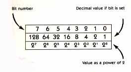
Note that each bit doubles in value as we go from right to left. We are, in effect, counting in powers of two. If a bit is not set, the value of that bit is zero. Thus, to determine the value of a byte, add up the values of all the bits that are set. Remember, position counts.
With this system, the highest number that can be represented in eight bits is 255, if all bits are set. But note that 256 numbers can be expressed. All bits off equals zero, and to the computer, zero is as important a number as any other. This may sound trivial, but as you get into more advanced programming, keeping this fact in mind can save you a lot of debugging time.
WHAT CAN IT DO?
Contrary to popular lore, the CPU doesn't really "know" numbers (binary or otherwise). All it knows is that voltages on certain lines cause predetermined changes to take place in other circuits. Chip designers have taken care to see that the results of these circuit changes can be interpreted in various ways. Once a value is in the accumulator, many other operations are possible. For example, if you send the value 169 to the 6502 chip, followed by the value10, the chip will "load" 10 into a part of itself called the "accumulator."
The chip's repertoire is extremely limited. Basically. it can add, subtract, compare two numbers, perform simple versions of IF/THEN and GOSUB commands, and move data around in memory. These talents certainly won't qualify the 6502 for a stage career. Yet, from its humble (but very fast) skills, all the wonderful graphics and computational capabilities of today's software have evolved.
Physically the Atari OS is contained in several integrated circuit (IC) chips that are separate from the CPU. In the Atari 800, the OS is easily removable. It resides on the first large cartridge (sometimes called a board) in the memory bay under the removable top. Ranked behind it are the RAM cartridges. The OS is stored in fixed position in memory (locations 55296- 65535); this position is located at the very top of the available memory space.
SPECIALTY CHIPS
What are the resources that the OS must manage? In addition to the microprocessor chip and RAM memory, there are four specialized chips that aid the 6502 in performing its job. These are ANTIC (that name sounds familiar), GTIA, POKEY and PIA. The workings of these components must be integrated with those of the 6502, a job at which the OS excels. A short description of each of the specialty chips is given below:
GTIA (memory locations 53248-53505)
This Television Interface Chip was designed to process the video signal. Early versions of the Atari had a CTIA. The difference between the two chips is that GTIA supports Graphics Modes 9-11, while CTIA does not. Basically, GTIA converts digital commands from ANTIC into a video signal that is sent to the television.
The data from ANTIC contains information for the Graphics Mode desired. While processing this data, GTIA adds its own information, which includes color values and Player/Missile graphics. GTIA also provides collision detection. (Collision for the player/Missile system is defined as two objects overlapping on the screen.) Finally, this busy little chip monitors the console keys.
ANTIC (locations 54272-54783)
This chip is actually a specialized microprocessor in its own right. It controls the screen display through instructions to C/GTIA. ANTIC has its own miniprogram called the display list. Upon a graphics call from BASIC, the Operating System sets up the display list at a specific spot in RAM. The display list then tells ANTIC exactly how to set up the TV screen and where to find the data to be displayed. ANTIC retrieves the display data and instructions from the display list and translates them into instructions for C/GTIA.
POKEY (locations 53760-54015)
POKEY is the digital I/O (Input/Output) chip. It has a multitude of functions. The chip has four independent sound channels. Each channel has a frequency register and a control register that regulate sound volume and distortion. You access these through the SOUND command from BASIC. You can also POK directly into these registers if you wish! POKEY reads values from the joysticks and paddle controllers. It also scans the keyboard for input, operates random numbers and handles serial I/O (i.e, communication with peripherals, such as a cassette recorder). "Serial" simply means that data is sent one bit at a time. "Parallel" means that more than one bit is sent at a time -- usually eight bits in the Atari.
PIA (locations 54016-54271)
The Peripheral Interface Adapter is a specialized microprocessor chip used to control the four controller jacks (the plugs used to connect joysticks and paddles).
It is now time to explore the subterranean caverns of the Operating System itself. Let's take our flashlights and maps and explore each of the main elements of the OS.
MONITOR
Don't confuse this with a television monitor. When you turn on your computer (this is called a "coldstart"), the computer must be set up in a standard way before it can release control to a language (such as BASIC). The monitor is a machine-language program th at performs this vital function. One of its first actions is to determine how much RAM it has to work with. This is done by checking the first byte of each 4K block of memory. If a value can be stored and recovered from that byte, that 4K block is assumed to be functional.
The total memory available, counted in "pages," is stored at memory location 106 (called RAMTOP). A page of memory is defined as 256 contiguous bytes whose first byte is evenly divisible by 256. To find the total memory available for your use, multiply the value found in RAMTOP by 256. You'll find that available memory is always less than the amount installed in the computer. This is because some of the memory is appropriated for use by the OS, the 6502 chip and BASIC.
The monitor performs many other functions during a coldstart. It clears all of RAM (by setting each location to zero) and initializes "pointers" (locations that contain the address of a particular table or routine). It then proceeds to initialize (set up) the device handlers. These are machine-language routines that control the editor, screen, keyboard, serial printer and cassette recorder. The monitor also determines whether a cartridge is installed and, if so, prepares for its subsequent use. Finally, it checks to see if a machine-language program needs to be "booted" in from cassette or disk.
BOOTING
The term "boot" is a piece of jargon that derives from the word "bootstrap, which was made famous by the phrase, "lifting yourself up by your own bootstraps." Bootstrapping is a technique by means of which a program brings itself into an operating state by its own action. Thus, the monitor contains a bootstrap loader, a routine that is capable of reading the initial instructions of another machine- language program. The program being read is set up so that its initial instructions cause the rest of the program to be loaded (i.e, it is a "bootable" program).
When all of this has been accomplished, the monitor releases control to the installed cartridge or the booted program. If neither is present, the Operating System goes into "memo pad" mode. In this mode, anything you type will appear on the screen, but nothing else will happen.
The monitor also handles the RESET sequence, which occurs when you press the [SYSTEM RESET] key. This is termed a "warmstart." Many of the functions of a coldstart are also performed during RESET. One of the big differences is that RESET clears only the RAM area used by the OS. Your BASIC program is not wiped out, as it would be if you turned off the computer.
There are a number of tricks we can play with the monitor. For example, we can go through the coldstart sequence without shutting off the computer. Simply POKE a one into location 580 and then press the [RESET] key (but remember that you'll erase any program in memory! ). This has a number of uses. If you POKE this location from within a program, you can prevent users from gaining control of the program while it's running. If they press [RESET], the program will be erased and they'll have to start over. A more sophisticated use of this technique is to use it with a disk- booted program. In this case, if the [RESET] key is pressed by accident (or design), all is not lost. The coldstart sequence will automatically reboot the program.
INTERRUPT PROCESSING
The interrupt system is one of the most powerful tools available to the creative programmer. This capability is built right into the 6502 microprocessor chip.
As computer jargon goes, the term "interrupt" is descriptive. There are two special pins (electrical connections) on the 6502. When the normal voltage to either of these pins is lowered, this "interrupt" signal tells the microprocessor that some outside event is demanding its attention. The 6502 completes the instruction it is working on and then saves necessary information so that it can eventually return to the correct place within the main program. It then goes to a pair of specific memory locations where it finds the address of a machine-language routine to execute. The chip begins executing the machine-language instructions at the new address until it encounters the code for an RTI (Return from Interruptj instruction. When the RTI is found, the chip goes back to the main program, retrieves the saved data, and then nonchalantly continues on as if nothing had happened. Since the interrupt routine is short and the microprocessor is very fast, the observer isn't even aware that the chip is playing hookey from the main program.
Corresponding to the two 6502 pins, there are two types of interrupts:
NMI (NonMaskable Interrupt)
IRQ (Interrupt Request)
The IRQ's can be turned off so that the chip won't respond to them. This is done by a machine-language command which, unfortunately, disables all the IRQ's. NMI interrupts cannot be turned off at the processor chip. But to allow for greater flexibility in interrupt usage, the folks at Atari routed many of the interrupts through the helper chips. For example, some NMI's can be controlled by POKE commands to certain control registers before they reach the 6502. ANTIC controls the NMI's; POKEY and PIA handle the various IRQ's.
VBI'S AND DLI'S
Two NMI's provide the bulk of the graphics and animation power that is available to machine-language programmers. These are the Vertical Blank Interrupt (VBI) and Display List Interrupt (DLI). An understanding of VBI's requires a short disgression into the workings of your television.
The television screen is lit by an electron beam that sweeps across the face of the TV tube and hits phosphors. A full scan is completed in roughly one sixtieth of a second. At the end of a scan, the electron beam is turned off and aimed again at the top-left portion of the screen in preparation for a fresh scan. The period during which the electron beam is off is called the vertical blank. Machine-language programmers take advantage of this time to make graphics changes and move players and missiles. Since these changes are made every sixtieth of a second, the resulting animation is smooth and clean. Another use for the VBI period is to play music or produce sounds that are independent of the main program.
During the VBI, the OS performs a number of housekeeping tasks. These include incrementing or decrementing different timers, updating readings from controllers and copying data from one register to another. Two addresses are used to help the processor find the VBI routines. The programmer can change these addresses to force the 6502 to perform a different routine. Of course, one must be careful to direct the 6502 back to Ihe correct place in the VBI routine.
Otherwise, the 6502 will run out of control, causing the computer to become unresponsive to commands. If this happens, the only solution is to turn the computer off and then back on. The system monitor will then come into play and initialize the computer's memory registers properly. As a result, the beast will once again become domesticated.
INTERRUPTING THE DISPLAY LIST
Remember the display list, the miniprogram used by ANTIC to control the screen display! The programmer can modify one of the display list instructions to cause an interrupt (called a display list interrupt or DLI) to occur at a precise scan line on the screen. The 6502 will then go to a certain memory location, get an address, go to that address and execute the program it finds there. Of course, the programmer must have previously loaded his DLI program into memory and placed the program address in the proper place.
At the start of each screen scan line there is a period during which the electron beam is off. This is called the horizontal blank. Any changes made during this time will not be seen until the electron beam is turned back on. Again, this allows neat, clean graphics to be made. The time period of the horizontal blank is much shorter than that of the vertical blank. Thus, only a limited number of changes can be made during a single DLI. But since a DLI can be set at every screen scan line, if desired, this can be a very powerful tool. For example, multiple players can be made to appear on the screen when the program is actually using only one player. At various positions on the screen, DLI's can be used to change a player's horizontal position, or even its image. Joust is a good example of this technique. I've provided a useful DLI routine, to be used from BASIC, in the paragraphs below.
PLOTTING COLORS
If you've read the BASIC manuals, you know that Graphics Modes 3, 5 and 7 are four-color modes. One color is used for the background. So, in theory, you can plot independently in three colors. If you are using a text window, however, you will find that things aren't that simple. The problem is that the same color registers are used for plotting on the graphics screen and for text in the text window. The choice of certain plotting colors can ruin the text display. The table below and the demo in Listing 1 illustrate the problem.
The short demo first plots three bars that correspond to COLORs 1, 2 and 3. The program then changes the bar colors, using the SETCOLOR command, to illustrate how the text window is affected. Then it installs a DLI routine and again changes the bar colors to demonstrate that the text window is now independent of color changes in the graphics window. The demo will cycle between the two conditions until you press [BREAK]. The DLI gives you the freedom to choose any color you wish in Graphics Modes 3, 5 and 7. It works by resetting the color registers that control the text window to their normal values. This is done just before the electron beam scans the text window. You can gain the same independence in your own work by incorporating lines 150-200 into your programs.
IRQ'S OF INTEREST
In contrast to the NMI's, the IRQ's are not often used by the programmer. Two IRQ's of interest are the [BREAK] key and the keyboard. Any time a key is pressed, an interrupt is generated that causes the OS to process the signal coming from the keyboard. A knowledgeable programmer can redirect this interrupt so that certain keys are ignored. For example, you can disable the [BREAK] key so that it is ignored while your program is running:
A = PEEK(16):IF A >= 129 THEN A = A-128:POKE 16, A:POKE 53774,A
Certain commands such as an OPEN to S: or E:, any GRAPHICS statement or a PRINT statement to the screen will reenable the [BREAK] key. In those cases, you will have to repeat the above code as necessary. Note that pressing [RESET] will also reenable the [BREAK] key.
Many of the other IRQ's are used by the OS to perform I/O, as with the cassette recorder.
That's it for now. Until next issue, I'll leave you in the midst of the OS (I hope you're not too lost). In Part II, I'll cover the rest of the Operating System. Keep your flashlight handy.
Fred Pinho is a biochemical research engineer and a self-taught programmer who Is interested in BASIC and assembly language. The Atari 800 is his first computer.
Listing: CINDER1.BAS Download