ATARI CONTROLS YOUR ENVIRONMENT
Simple computer appliance interface
SYNOPSIS
A computer-appliance interface (CAI) is a device that lets you control appliances and other machines with your computer. Although building a CAI is not an extraordinary complex project, you should be experienced with electronic circuit assembly before you attempt it. You must build the circuit to use the programs in this article. Do not use these programs with a joystick, or you may damage your computer. This CAI and its programs work with Atari computers of all models and memory configurations.
Atari home computers are capable of much more than just playing games and tackling traditional programming applications. The Atari's four game controllers (two on XL models) contain sixteen lines (eight on the XL series), each of which can be set for input or output. This offers the user up to 65,536(216)possible external operations.
This article explains how to set one line to output, how to turn aplliances on and off, and how to dial your phone under computer control.
WHAT IS A CAI?
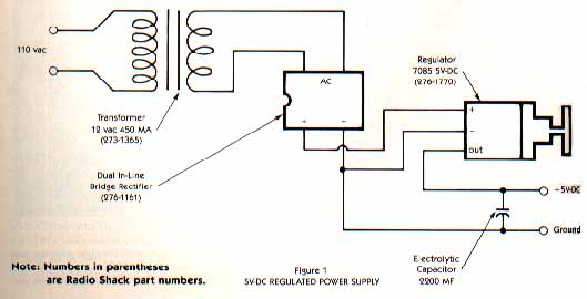
The computer-appliance interface (CAI) consists of the following circuits: a regulated 5V-DC power supply; a two-stage inverting buffer; an infrared optoisolator; a single-stage transistor amplifier; a micro relay; and a macro relay.
The power-supplv circuit (Figure 1) was constructed from readily available parts, and is much larger than necessary. You can add one control-line circuit.
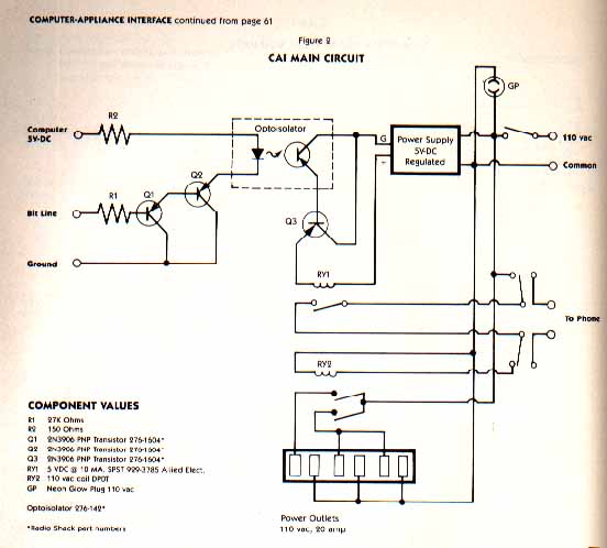
The main circuit (figure 2) shows the interconnection of the two-stage inverting buffur, the optoisolator, and the amplifier that powers the micro relay. The optoisolator acts as a physical barrier between the computer and the 110V-AC, circuit that is being controlled. Without this protection, the computer could be electrically zapped and destroyed (see ANTIC, Systems Guide, March 1984). All parts except the micro relay are available from Radio Shack.
The micro relay, manufactured by Struther Dunn, Inc., is available from Allied, Inc., 1355 North McIean Blvd., Elgin, IL. Insert it into an IC socket fur easier installation.
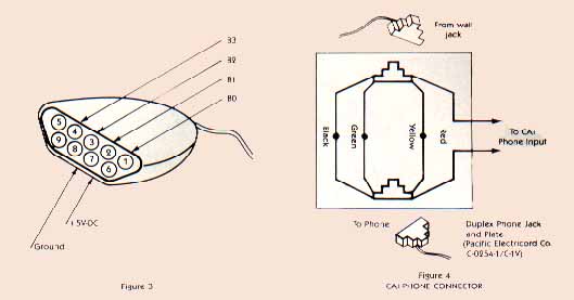
You'll need a DE9S connector to plug the CAI into your computer's joystick port. These are available from Atari, Radio Shack, and electronics partr stores. Figure 3 shows you which pinouts to use: Our device will use pin 3.
Soldering the connector pins to th cable's wire ends and putting on the shell are quite difficult jobs. You must be both experienced with soldering and patient to complete them successfully.
WARNINGS
Before you attempt to build the circuit or use its associated programs, please note the following warnings:
- If you attach any non-standard device to your Atari computer, your warranty will be voided.
- You should never use either of the programs included in this article with a joystick attached to your computer. This could short a line and destroy the PIA chip.
- The 110V-AC power lines constitute a potential shock hazard, and must be carefully insulated.
BUILDING THE CAI
The location of parts isn't of critical importance. I used a three-and-a-half-inch by six-inch perf panel as a base, and attached the transformer, macro relay, and cables to it. The power supply and the optoisolator/detector circuit were assembled on separate pieces of printed-circuit (PC) board. These were then attached to the main perf board.
The iptoisolator consists of two components: an infrared emitter and an infrared phototransisstor. To insure maximum coupling, these components should be mounted on PC board so that they almost touch, a small piece of black shrink tubing is then slipped on to hold them in alignment. Care must be taken to insure that the cases don't come in contact, however, since this would compromise the optoisolator's function. If black shrink tubing isn't used, the optoisolator will be exposed to ambient light and may not function yroperly.
A miniature, dual-inline, reed-type micro relay can be inserted into a standard IC socket, which in turn can be mounted on the PC board. The socket's pins protrude through the back of the PC board, and it is to these pins that connections should be made.
The relay's pin-outs follow standard IC labeling practice. Pins 2 and 6 are used for coil power; pins 8 and 16 are relay contacts.
Use the specified micro relay. Other available micro relays draw more current, and may not work in this application. If you must substitute another device, make sure that its coil draws less than 10 milliamps at 5V-DC. On the other hand, any 11OV-AC-coil, general-purpose macro relay should work. Its specifications aren't critical.
ADDITIONAL WARNINGS
Once you've built the CAI, resist the temptation to try it out right away. Before exposing your expensive and delicate computer to this strange device, run a bench test to make sure that neither the power drain on Bit Line 3 nor the computer's power supply exceeds specifications.
To do this, you'll need a Simpson 260 test meter or its equivalent. First, set the test meter to the 100-milliamp scale and connect it in series from the +5V-DC connection on your power supply to pin 7 on the connector. Next, connect a shorting line to pin 4, and prepare to touch the other end to the ground on the power supply. When you insert wires into the connector, be careful not to damage the receptacles by using excessive force or a wire that is too large. Touch the shorting line to the ground. You should hear the macro relay "pull in," and your meter should read less than 50 milliamps.
Next, remove the test meter and set it to the l0-milliamp scale. Connect the +5V-DC pin directly to pin 7 and reconnect the test meter in series with your shorting line. Now, connect to ground. Again, you should hear the macro relay pull in, and your meter should read less than l.6 milliamps. If these tests don't produce the expected amperage values or if the relay doesn't pull in, something is wrong. Stop and check for shorts, the incorrect wiring of transistors, etc. Don't use the CAI on your computer until everything checks out.
USING THE CAI
When these bench tests produce the proper results, type in the driver program, connect the CAI to Port 1, set it for an appliance, and you're ready to go. The CAI also has a telephone interface. Use Figure 4 to connect your phone to the CAI. Then type in the phone-dialer program (Listing 2), remove the phone from its cradle, and type in a phone number.
"Pulse" phone dialing is accomplished by opening and closing the phone circuit quickly, creating a "pulse series," and by holding the phone circuit closed for a short time between series. Phone-number digits are coded so that the number "3" equals three pulses, "6" equals six pulses, etc. Zero ("O") is coded as ten pulses.
This article deals with only a few of the ways in which you can interface your Atari with the outside world. Other possibilities include adding a four-to-sixteen-line decoder that would provide you with control of as many as sixteen devices from one port plug, and remote control of the appliances in your home via your Atari.
Jeff McHie, a fifteen-year-old high school sophomore who lives in South Holland, Illinois, is currently, studying mainframe programming. His other computing interests range from writing machine-language arcade games to building a "stand-alone" computer dedicacted to home security and energy conservation. Jeff has heen exposed to computers from the first grade on, and is a member of Computer Squad, a Iocal Atari Users' group.
TAKE-APART FOR PHONE-DRIVER PROGRAM
Line 10 Dimensions A$.
Line 15 Prompts user to select either toll-free or local-call format.
Line 20 Prompts user to input number to be called.
Line 25 Disconnects phone for a short time to clear any previous call. Sets Z1 flag (Z1=1) if toll-free option was selected.
Line 30 Informs user that a call is being processed and suppresses cursor.
Line 40 Starts output sequence.
Lines 60 & 61 Connect phone and pause for a short time to obtain a dial tone.
Line 65 Retrieves one element of A$ at a time and forces its numeric value into variable C.
Line 66 If a zero is encountered in variable C, it is converted to 10. A zero must be transmitted as ten pulses to conform to protocal.
Line 70 Transmits pulses to the phone; the number of pulses to transmit is defined by lines 65 and 66, and is forced into variable C.
Line 75 Checks to see if flag Z1 has been set (Z1=1), indicating that a toll-free number has been input. If so, the program branches to line 270, which checks for hyphens at three locations in the phone number.
Line 80 If the branch at line 75 did not occur, this code -- which checks for only one hyphen -- is run. Variable B(the current element) is incremented. When B=4, indcating that a hyphen numeric value is to be forced into variable C, B is incremented again so that the pulse-generation code will receive the next digit, rather then ASCII value for a hyphen.
Line 90 Checks to see if the last digit of the phone number has been processed. If not, the program continues to line 95. If the last digit has been processed, the code resets flag Z1 to zero, resets B to 1, clears the screen, turns cursor back on, and returns to line 15.
Line 100 Loops back to line 65 to pick up the next digit for processing.
Line 150 & 200 Promts the user regarding the "800 number" input format.
Line 250 Turns the phone line off.
Line 260 Sets the number of elements to be processed to 15 by setting Z2=15
Line 270 Checks for three hyphens and skips over them when they occur. Increments variable B to select the next digit to transmit, and loops back to transmitting code.
Line 275 Loop back to transmitting code.
Listing: PHONDRIV.BAS Download