LITTLE BROTHER GROWS UP
An audio/visual output mod for the 400
SYNOPSIS
This article explains how to adapt an Atari 400 for audio and video output. The project involves wiring and building a circuit board, so you should be faily experienced with electronics before undertaking it.
If you've installed 48K and a good keyboard in you Atari 400, you know that it's as capable a computer as its big brother, the 800--with one exception. The 400 does not provide a DIN jack for audio and video output.
If you attach a high-quality color monitor to your 400, this will improve its graphics so much that you'll practically be able to "see the whites of your enemy's eyes." Similarly, if you connect the 400's audio output to a stereo, you'll be able to hear the "crash thunder" as you destroy him. This article explains how to accomplish both of these goals for $20 and a few hours of work with a soldering gun.
BUILDING A CIRCUIT BOARD
Our goal is to build a circuit hoard, and then connect it to a 400's motherboard. (To undertake this project, you should be fairly adept at soldering. If you've assembled a Heathkit, you'll probably have no trouble.) Most of the component values are not critical, so feel free to experiment if your component doesn't have the exact value noted here. All components should be available from a local electronics store. The new output jack we're creating will provide the following features: composite luminance, composite video, composite chroma and audio output.
Figure 1 shows a suggested layout for the circuit board. The small size of the board and the vertical mounting of resistors are necessary because of the limited amount of space within the 400 case. We recommend using a glass-epoxy "perf" board with point-to-point wiring. This circuit board comes with holes already drilled; buy the type with O.lO-inch hole spacing. Try parts out for size and fit before you cut the board.
The layout of parts is not critical, but you should try to keep leads as direct as possible. Use 24-gauge, solid wire for on-board connections. "Flea clips" can be used to mount components. These small, U-shaped metal clips are pointed at one end, which can be inserted into the perfboard. Integrated-circuit (IC) chips should be mounted in sockets.
AUDIO OUTPUT
U1 (Figure 2) is a CMOS hex buffer (high-impedance input and low-impedance output), which is followed by a resistive-combiner network. Q1 and Q2 are emitter-follower amplifiers; they provide current gain for the low-impedance video outputs. U2 is an audio-power-amplifier IC. Its audio output (approximately 1/8 watt) will drive a good-sized speaker. An outboard potentiometer can be added to control volume (250 ohms). Output can also be used with the auxiliary input of a stereo system.
U2 (CD4050) is sensitive to static charges. For example, if you place the circuit board on a sheet of aluminum foil and touch the IC's conductive foam or plastic packaging to the foil, one zap of static discharge will destroy the chip.
RG-174 coaxial wire can be used for the video outputs; use stranded 24-gauge wire for all other lines. No heat sink is required for the audio Imp IC (U2).
INSTALLING THE BOARD
When you're ready to install the board, you'll need to disassemble your 400. First, disconnect all cables and remove any cartridges. Then turn it over and remove the screws that hold the upper and lower halves together. Once this is done, detach the keyboard and remove the large metal "shielding" casting. This will expose the section of the main board to which your modified board will be added. (Take careful note of where and how the pieces come apart.)
You'll have to cut a slot in the rear of the metal housing (in the lower left-hand corner, as viewed from the rear of the 400) to create an exit for video and audio cables. Well drilled a 3/8-inch hole and then made two cuts with a hacksaw to form a slot. Be sure to keep metal filings away from the circuit boards, clean the housing very carefully, and round off the corners of the slot with a file to protect the cable's insulation. In addition, cut the three vertical ribs in the plastic case (next to the TV-channel select switch) to provide an exit for the female DIN jack.
INTERFACE CONNECTIONS
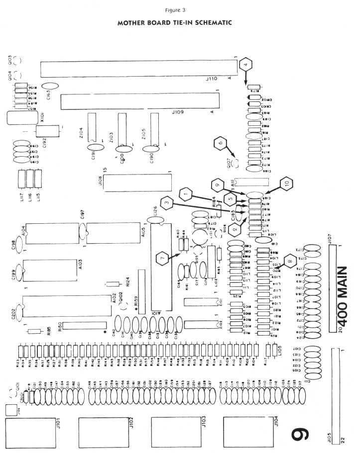
Figure 3 shows the locations of the interface connections on the motherboard. Care should be taken to avoid heat damage to the board. ( points indicated.) Be sure to adhere strictly to the indi- cated locations, components, and sides for connections. Do not change or reverse any of these connections, espe- cially C 183 (the SV-DC/ground connection)!
No further adjustments are necessary, and this new board will not affect the RF output to your regular T.V. Simply use the composite-luminance output and ground for a monochrome monitor and the composite video and ground for a color monitor. Sound is supplied by the audio output and ground.
ADDITIONAL PRECAUTIONS
To keep the board from shorting out, wrap it in black-cloth electrical tape, rather than plastic tape. Make up a female DIN plug connection (plug side), and then make connection to your new board. This will keep things neat. Also, provide a "strain relief" that will keep you from pulling the wiring loose when you disconnect the monitor cable. We suggest that you use a good-sized wire tie around the lines that go out to the female DIN plug, just inside the metal shielding case. This will provide relief when the external monitor cable is detached; the female DIN plug (keep it short!) will take care of insertions.
While we're discussing "strain reliefs," note that in Figure 1 the lines leaving the board are on the top outside row of the holes. This result is accomplished by enlarging these holes slightly to allow insulated wire to pass through to the bottom of the board. This keeps the connections from being pulled loose.
Also, note (see Figure 1) that we've "notched" one corner of the board to help trace the circuitry. Where wires join, a black dot is shown. A "jump-over" is indicate where wires cross without joining; a hole is shown where a wire passes through the board. If you encounter any trouble in completing this modification, trace your circuits using the schematics shown in Figures 2 and 3. They' re the "source" for the board shown in Figure 1.
COMPONENTS
Resistors: 1 @ Ik, 3 @ 2.2k, 1 @ 4.7k, 1 @ 9.lk, 1 @ 18k, 3 @ 20k, 1 @ 36k, 1 @ 40k, 1 @ 75k, 1 @ 120k, 1 @ 220k and 1 @ 330k(all 1/4w - 5%)
Capacitors: 1 @ 100mf, 1 @ 100pf and 3 @ O.lmf(5-16 VDC)
Transistors: 2 @ 2N2222
Diodes: 1@1N4148
Chips: I @ CD4050 hex buffer and 1 @ LM386 audio amp
Miscellaneous: Glass-epoxy perforated board (4" x 6"), RG-174 coax cable (3 ft.), 1 @ 8-pin wire wrap IC socket,1 @ 16-pin wire wrap IC socket and 1 @ female DIN plug with boot.
Figure 1
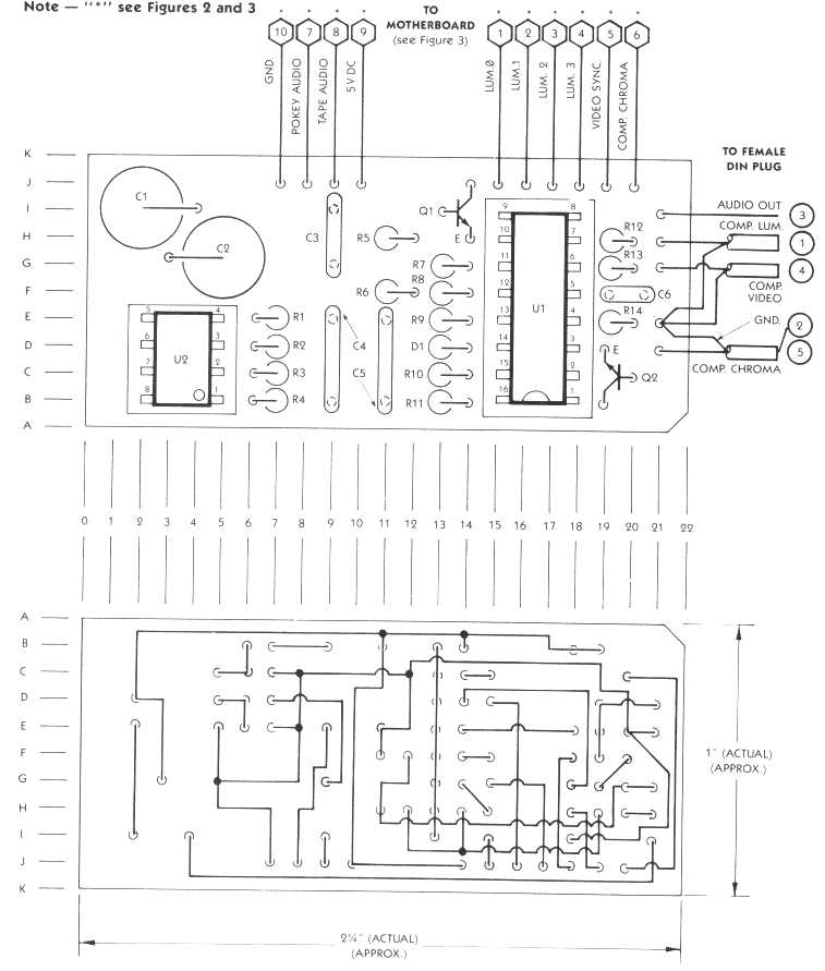
Figure 2
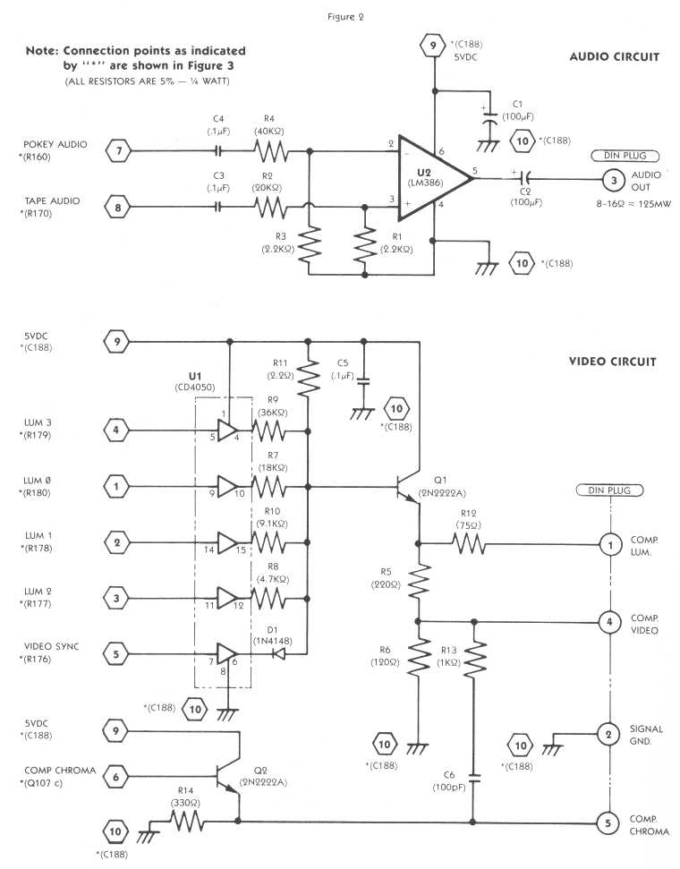
Figure 3
Jim Lee and Dick Slavens are residents of Napa, California. Jim is a design supervisors for the Bechtel Group, Inc., of San Francisco. Trained as an architect, he designs refineries, chemical plants and nuclear fuel processing facilities. Dick does telecommunications work for Pacific Gas & Electric, also in San Francisco. He originally bought his 400 as a game machine. Feeling constricted by its limitations, however he worked to improve his machine. This article is a direct result ofthose efforts.