DOT-MATRIX DIGITIZER
Your printer can digitize photos!
by CHARLES JACKSON & STEVEN CHAPMAN
Turn your dot-matrix printer into a photographic digitizer for a
couple of dollars in electronic parts and some surprisingly simple tinkering.
The included BASIC program requires an Atari computer with the GTIA chip,
and a disk drive.
To test whether your Atari has the GTIA, type in and RUN
the following: 10 GRAPHICS 9:GOTO 10. If your screen turns black,
you have the correct GTIA chip. If it remains blue, you have the
older CTIA chip.
Your dot-matrix printer can digitize photographs.
The parts you'll need should cost less than $3. With the accompanying digitizer
program, you can create and store beautiful digitized GRAPHICS 9 pictures.
Then you can use Scott Berfield's "GTIA Sketchpad" program (Antic, December,
1983) to edit and print out your pictures!
To test whether your Atari has the GTIA, type in and RUN the
following:
10 GRAPHICS 9:GOTO 10. If your screen turns black, you have the correct
GTLA chip. If it remains blue, you have the older CTLA chip.
As written, the digitizer program is for the Gemini 10-X printer.
But we'll tell you how to modify the program for other printers.
However, first you must do a bit of easy tinkering. Here's the
hardware you'll need:
- TIL414 Infrared phototransistor (Radio Shack 276-145 or equivalent).
- Female joystick port connector (Radio Shack 276-1538 or equivalent).
- BIC-type pen cap.
- 150-watt (at least) light source
- Several feet of cable wire, plus aluminum foil, paper clips and electrical tape.
Assemble the digitizer circuit as shown in Figure 1. If you own an XL computer, bend back the joystick port connector's metal flap or it won't fit.
The pen cap will hold the phototransistor, shielding it from heat and stray light. Cut off a half-inch from the top of the pen cap to form a tube. Slide the phototransistor into the pen cap (push it as far as it will go) and tape the wires to the pen cap's clip.
Seal the back of the pen cap with a small piece of electrical tape to keep out stray light.
Cut a small slit in a piece of electrical tape, and place it over the front of the pen cap. This slit acts like a glare guard for the phototransistor.
Next, take a small piece of aluminum foil, wrap it around the pen cap and tape it in place. The foil prevents stray light from passing through the pen cap to the phototransistor. It also protects the phototransistor from much of the heat generated by your light source. Signs of an overheated phototransistor include random black spots on your digitized picture. Make sure the foil doesn't block the sensor's front slit.
PRINTER ATTACHMENT
Turn off your printer and unplug it. Remove the tractor feed unit and
ribbon, and adjust the roller bars to press the paper flat against the
platen.
Bend a paper clip into an "L" shape and attach it to the print
head screw. (See Figure 2.) Tape the light sensor to the paper clip. Position
the sensor above the roller bar, at a right angle to the picture and about
one-half inch away from it. Tape the sensor's wires to the print head.
This will help the sensor stay in place while the print head moves.
DIGITIZING
Type in the digitizing program, check it with TYPO II and SAVE a copy.
Select a large black-and-white photograph with plenty of contrast.
Portraits are best to start with.
We found that the digitizer doesn't work well with glossy photographs.
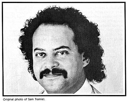
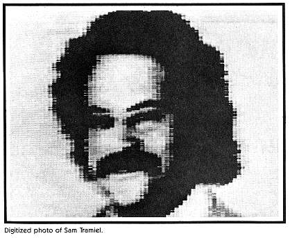
So use a photocopy of any glossy picture you want to digitize. The sample
digitized illustration with this article was made from a photocopy of an
8" X 10" glossy photo of Sam Tramiel, president of Atari Corp.
The digitizer will process an area measuring up to 5 1/3 inches
high by 8 1/4 inches wide. Turn off the power to the printer and insert
your picture as you would any piece of paper. Check the DIP switches
on the rear of the Gemini. Switches 1-3 should be turned down and switch
4 should be up.
These switch settings tell the Gemini to ignore the "paper-out"
detector, and to print the contents of the buffer and a linefeed every
time it receives a carriage return code.
Position your light source above the photograph. Make sure the
light sensor will not be "reading" its own shadow.
Bright fluorescent lights are preferable to incandescent lights
because they provide an even, glare-free glow which does not radiate much
heat. If a fluorescent light is not available, two or more incandescent
lights should be used to ensure even lighting.
Plug the sensor into joystick port 1 and type in this one-line
calibration program:
1 PRINT PADDLE(0):SOUND 0,PADDLE(0),14,14: GOTO 1
Turn on your light source(s) and type RUN. The program prints light
levels onto the screen while generating corresponding sound cues. Light
levels range from zero to 228. Low numbers and high tones indicate bright
light. High numbers and low tones correspond to dimmer light. Adjust the
lights so that white areas of the photograph return high tones and low
numbers, while dark areas return low tones and high numbers.
Turn on the printer, LOAD the digitizer program and type RUN.
The computer will ask you for the filename under which your completed picture
will be stored, and the type of digitizing process to be used. The "High
Contrast" option uses a formula which normalizes light levels and increases
the program's sensitivity to lighter areas.
The program must calibrate itself before digitizing your photo.
The computer will prompt you to put a white screen or card in front of
the sensor, then a black screen or card. Once you've calibrated the program,
press [RETURN] to begin digitizing and the printhead will move back and
forth.
The computer requires 20 minutes to digitize a picture using
the "Low Contrast" option. Pictures processed with "High Contrast" require
60 minutes.
After about seven minutes, the screen will change colors and
enter the "attract mode" to preserve the life of your picture tube. Press
any key when you want to restore the proper colors to your screen.
HOW IT WORKS
Line 190 places the printer in condensed mode (136 characters per line).
At line 250, the print head moves to the last column, advances the paper
by 4/l44ths of an inch, and tries to print a period. But the print head
is already against the right margin, so it must do a carriage return before
it can print the period. The carriage return and print instructions are
stored in the printer's buffer. While the print head is returning to the
left margin, the computer is free to perform other operations, such as
reading the light sensor.
Your original picture will not be harmed, because the printer
does not actually print a period. Line 170 instructs the printer to use
a downloaded character set. Since we haven't downloaded a character set,
the printer prints blanks. As no characters are ever printed, the print
head remains cool.
During each carraige return, the computer reads the light sensor
80 times; once for each pixel in a GTLA screen scan line. The scanning
loop routine lies in lines 260-280. Line 270 is an arithmetical delay which
slow down the scanning loop. If this line were omitted, the scanning loop
would be completed before the entire line could be scanned, and the digitized
picture would be stretched horizontally.
A sound cue has been included to let you know when the computer
is reading the light sensor. Use this cue to adjust the duration of the
scanning loop when you use the digitizer with other types of printers.
OTHER PRINTERS
To use the digitizer with other printers, you must change the following
printer control codes. If your printer has an adequate manual, it will
chart the codes that control these functions below:
Line Purpose
170 Select the download character set.
180 Set the linefeed value to zero.
190 Put the printer in condensed mode.
200 Move the left margin to column one.
210 Ignore the "Paper-Out" detector.
220 Move the print head to the left margin.
250 Move the print head to the right margin,
then advance the paper by 4/144 inches.
Steven Chapman is a design student at UCLA, concentrating on real-world computer graphics applications. He sent Antic his highly original method of interfacing a pre-Selectric typewriter as a photo digitizer When time came for Charles Jackson, our in-house programming specialist, to finalize the digitizer material for publication, he realized that the project would be useful to a lot more readers if it used dot-matrix printers instead. So, with Chapman's conception as a starting point, he built a new interface, reprogrammed the software and wrote a new article.
Listing DIGITIZE.BAS Download