Morse Code Reciever
Atari dots and dashes, 70 words per minute
by STEVE STUNTZ
Morse Code Receiver translates Morse code into ASCII values which your Atari displays as letters or numbers. The BASIC listing creates an assembly language program. The assembly language source code is also provided, but you don't need to type it in. This program works with all 8-bit Atari computers, disk or cassette. You'll also need to build a simple, inexpensive interface described in the article.
"Can I interface my Atari 800 with a shortwave transceiver? I know Morse code can be generated, but can it be received and translated back to ASCII? What type of interface is needed, and what are the costs of such equipment?"
Bill Keaton
Amherst, Ohio
Connect your Atari to a shortwave radio? Of course! A few dollars for parts, a few hours of soldering and programming, and your Atari can translate Morse code as quickly as 70 words minute.
The program can also he used for code practice without the interface. Send code with a joystick, or by connecting a Morse code key to the joystick port. You will hear the Morse dots-and-dashes beeping and see letters displayed on the screen as you operate the joystick or key.
MORSE SOFTWARE
The program coverts Morse code at any speed between 5 and 70 words per minute, and it automatically adjusts to any speed changes.
The decoded messages are shown on the screen in inverse video. The message scrolls upward as it fills the screen, and a word wrap routine prevents words from being split at the end of a line.
Listing 1, CODEWRIT.RAS, is a BASIC program which creates the machine language object file called CODEWRIT.EXE. Type in Listing 1, checking it with TYPO II, and SAVE a backup copy to disk or cassette before you RUN it. Antic Disk subscribers use the L command in DOS to load CODEWRIT.EXE from the monthly disk.
The CODEWRIT.EXE file can be copied to another disk and renamed AUTORUN.SYS, so that it starts automatically when you insert the disk.
Listing 2, CODEWRIT.M65, is the corresponding assembly language MAC/65 source code. You do not need to type in Listing 2 to use the Morse Code Receiver program.
MORSE HARDWARE
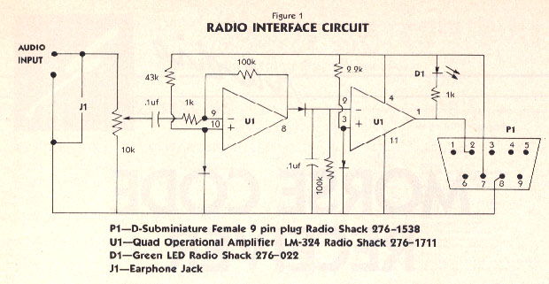
You can build the Atari/Radio interface for under $15. The complete parts list appears at the end of this article. Assemble the circuit as it appears in Figure 1. Note that a 33K-0hm resistor is connected in series with a 10K-Ohm resistor to duplicate a 43K-Ohm resistor (which was unavailable).
USING THE PROGRAM
To test the program, plug a joystick into Port 1. Quickly pull back on the stick and release it three times. Your monitor should beep three times, and a letter S should appear on your screen.
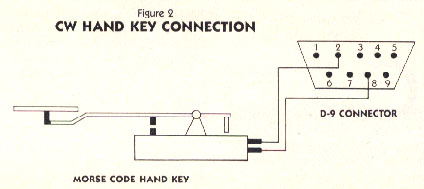
If you're teaching yourself Morse code, you can continue using the joystick as a Morse code key. Or you can connect a real key to the joystick port as shown in figure 2.
Now you're ready to receive some code. Boot the Morse Code Receiver program. Make sure the interface circuit is connected to joystick port 1.
Find a strong broadcast signal with little background noise. Plug your interface circuit into your radio's earphone jack. Carefully adjust the interface's potentiometer so that the LED blinks on and off in time with the code. In a moment, your Atari will display the decoded message, one letter at a time.
From time to time, the program may misinterpret one or two characters. This occurs because the program is adjusting its timing loop and does not yet have enough information to distinguish dots from dashes.
PROGRAM ANALYSIS
The timing loop (lines 1820-1970 in Listing 2) is controlled with display list interrupts. This loop checks the status of pin #2 of the joystick port. When the computer is receiving a signal (either a dot or a dash), this pin is grounded. Otherwise the pin is open.
The timing loop checks the status of this pin 120 times per second, and stores the number of interrupts occurring between each status change. This value is stored in the timing buffer. Each time the status of pin #2 changes, the number of intervening interrupts is stored in the next memory location of the timing buffer.
This process continues until all 256 bytes of the timing buffer are used. Then the buffer is cleared and used again.
The CW character loop (Lines 2000-2070 in Listing 2) determines if the timing buffer contains useful timing information. If this is so, the routine uses the timing information to begin reconstructing the proper Morse code character.
The program observes the following conventions when handling Morse code timing information:
1. A dot is represented by 0.
2. A dash is represented by 1.
3. A Morse code word is read from right to left.
4. The last 1 encountered when reading from right to left indicates the end of the character.
The routine will continue readng and decoding timing information until it encounters a character space. Then, the program looks up the ASCII equivalent of the decoded character, prints it to the screen and returns for more code.
For example, the letter A (a dot followed by a dash) sent at 18 words per minute causes the computer to store the numbers 8, 24, 24, 36 in the timing buffer.
Then the CW character loop converts those four numbers into one Morse character and finds its corresponding ASCII character to display on the screen.
Remember that the program needs a fairly clear signal to operate properly. However, I've managed to copy signals sent from locations all over the world.
PARTS LIST
D-9 Female Joystick Connector.
Radio Shack #276-1538 or equivalent.
LM-324 Quad Operational Amplifier.
Radio Shack #276-1711 or equivalent.
Green LED.
Radio Shack #276-022 or equivalent.
Three Silicon Diodes.
Radio Shack #276-1620 or equivalent.
10K-Ohm Linear Taper Potentiometer.
Radio Shack #271-1715 or equivalent.
Two 100K-ohm, 1/4 Watt Resistors.
Radio Shack #271-1347 or equivalent.
Two 1K-Ohm, 1/4 Wan Resistors.
Radio Shack #271-1321 or equivalent.
2.2K-0hm, 1/4 Watt Resistor.
Radio Shack #271-1325 or equivalent.
33K-0hm, 1/4 Watt Resistor.
Radio Shack #271-1341 or equivalent.
10K-Ohm, 1/4 Watt Resistor.
Radio Shack #271-1335 or equivalent.
Two 0.1uf Capacitors.
Radio Shack #272-135 or equivalent.
14-pin DIP Socket.
Radio Shack #276-1999, or equivalent.
Miscellaneous: Radio earphone jack and plug, wire, PC board.
Steve Stuntz is an electrical engineer from Loveland, CO.
Listing 1: CODEWRIT.EXE Download
Listing 2: CODEWRIT.M65 Download / View