BUILD THE WEFAX INTERFACE
by BILL MARQUARDT, Antic Technical Assistant
Here are the instructions for building the WEFAX hardware interface. This simple circuit will work with both the 8-bit and ST versions of the WEFAX program. Intermediate electronics tinkerers should be able to build the $20 project in a day with parts from a local electronics store or Radio Shack.
Before your Atari can receive WEFAX signals, you must build the WEFAX interface, a simple circuit which lets your radio "talk" to your Atari. You'll need only basic soldering skills and the ability to work from a circuit diagram to build this project. Experience with shortwave or amateur radio would also help. If you're lost, ask around at the next users group meeting. Someone there is likely to have the necessary skills and share your interest.
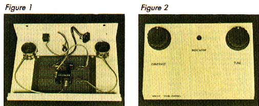
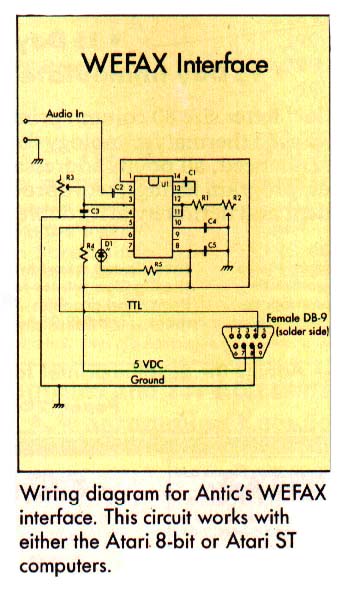
Antic's WEFAX interface. On the right is the finished interface. On the left the inside of the interface, showing construction details.
Antic spent several months experimenting with different circuits and testing various software designs for our WEFAX project. Keeping low cost, versatility reliability and ease of use in mind, we chose the accompanying circuit (Figure 1) as best. It is a variation of the linear FM detector found in Semiconductor Reference Guide, published by Radio Shack.
Although this circuit is designed for the 8-bit version of the WEFAX program, you can build a simple cable (Figure 2) and use it with the ST WEFAX program.
This project is relatively simple and should cause the average experimenter no problems. Power for the circuit comes from the 5-volt pin of joystick port 2. This decreases the possibility of faulty construction damaging your computer. As with any hardware project, careful construction techniques will greatly improve your chances of success.
The heart of this circuit is a XR 2211 FSK Demodulator/Tone Decoder chip. It's somewhat expensive, but it considerably reduces the number of other components you'll need--which in turn reduces the overall cost of the project. Currently, Radio Shack sells this chip for about $6.
HANDLING THE CHIP
Make sure you use a compatible socket for the XR 2211 - and don't insert the chip until the socket has been soldered in place! If you're a beginner, the socket eliminates the chance of the chip overheating while your're soldering. If you're an advanced "hardware hacker," the socket will let you remove the XR 2211 chip for use in other projects.
Although a standard DB-9 (joystick) connector fits comfortably into the front of an Atari 400 or 800, commercial DB-9s may require some sort of an extender to reach the recessed joystick ports on the XL and XE models. In this case, you must bend back the DB-9's metal tabs before it will fit. Or if you own the PaperClip word processor from Batteries Included, you can use the black extender from the program's "key."
Unfortunately, you cannot use the plug from an old Atari joystick because there is no connection to the 5-volt pin (pin 7). If you use a plastic hood with your DB-9 connector, it may need trimming.
TESTING THE CIRCUIT
Once you've constructed the interface, you can test it with Listing 5, WETST.BAS. Type in this listing, check it with TYPO II and SAVE a copy to disk before you RUN it. This BASIC program generates a wavering tone which we'll use to test our circuit. Make a 2-3 minute tape recording of this tone on a good tape recorder--preferably one which plugs into an AC outlet. Battery-powered tape recorders yield unreliable results.
Once you've made this test tape, stop the WETST program and run the main WEFAX Decoder program. Now, we'll use our test tape instead of a WEFAX signal. Plug your WEFAX interface into joystick port 2, and connect the audio output of your tape player to the input port of the interface. If you've built the circuit correctly, the test tape will produce a striped pattern on your WEFAX screen.
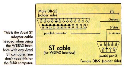
Wiring diagram for Antic's WEFAX interface. This circuit works with either the Atari 8-bit or Atari ST computers.
SHIELDING
Although we've had little trouble with our open-air prototype, you can mount your finished circuit board inside a metal box to shield it from interference. If you still have interference problems, use shielded cables.
The audio jack on your radio receiver should also be volume-controlled, or else you might need to add an attenuating potentiometer of 5K or 10K Ohms on the audio input to the circuit board. The circuit board itself can be of any of the various perf-boards at Radio Shack or other stores.
The timing for the XR 2211 is provided by the combination of resistor R1 with potentiometer R2 and capacitor C1. Adjusting R2 varies the center frequency of the chip's internal oscillator. The values of these components wrere chosen to give us a frequency within the range of our WEFAX information. The formula is:
f0=1/CR
PARTS LIST
                                 Radio Shack
Capacitors                 Part #               Price
C1,C2,
C4,C5  .luF               272-1069             .69
C3     .022uF             272-1066             .69

Resistors
R1      4.7K Ohms         271-030              .19
R2,R3   50K Ohms          271-1716            1.09
             Pot
R4      56K Ohms          271-043              .19
R5      150 Ohms          271-013              .19

Diodes
D1  LED                   276-068             1.59
(or equivalent)

Integrated Circuits
U1       XR 2211          276-2337            5.99

Miscellaneous
DB-9                      276-1538            2.49
female connector
Perfboard                 276-158             1.95
Socket,                   276-1999             .89
14 pin DIP
You will also need cables and connectors to connect the interface to your computer and radio. Types will vary according to your specific setup.
Listing:WETST.BAS Download