Easy 3-D Wire Frames
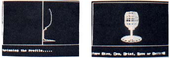
Spinning the shapes of your imagination
By ROBERT GEDDINGS
 |
Just draw a shape with your joystick and easy 3-D Wire Frames spins that shape into a complete three-dimensional wire frame graphic. This BASIC program works on all 8-bit Atari computers with at least 48K, Disk or Cassette.
A BLUEPRINT OF A HOUSE is a typical "wire-frame" graphic--a drawing composed entirely of lines, instead of a realistic "solid model" drawing of a house with everything colored or shaded.
Imagine being able to create three-dimensional wire frame graphics with no more effort than using a joystick to draw a single profile. That would be pretty nice, right? Well, you don't need to strain your imagination. Easy 3-D Wire Frames gives you that ability right now.
"With Easy 3-D Wire Frames, in a few minutes you can be designing an infinite variety of 3-D wire-frame spheres, cones, toruses, cubes, funnels and more. . . The number of different objects you can design is limited only by your imagination.
This program is an easy-to-use graphics system for creating realistic 3-D wire frame images. With Easy 3-D Wire Frames, you simply create an object's "profile" (one of its sides). The program "spins" the profile around a center line, creating the wire frame. Easy 3-D Wire Frames takes care of all the messy little details such as calculating all the data points, fitting the object to the screen and displaying it in three dimensions.
3-D TERMINOLOGY
Before starting to use the program, there are a few computer graphics concepts that you need to be familiar with.
Axis: Most computer users are familiar with the standard three-dimensional axis that has the X-Axis going left and right, the Y-Axis moving up and down and the Z-Axis giving the illusion of going forward and backward inside the screen.
Easy 3-D Wire Frames rotates this axis slightly in order to get a 3-D effect when viewing the image. The left/right X-Axis is unchanged, but the Z and Y Axis have been reversed. Now the Z-Axis is the up/down movement on the screen and the Y-Axis moves into and out of the viewing plane.
Translation: Moving an object along any axis is called a translation. Translating an object has no effect on how the object will appear, it is simply used to move the object to a different place on the screen. For instance, after you create an object, if it seems too high on the screen you can use translation to move it towards the center.
Yaw: The best way to explain what the next three terms mean is to compare them to something you do every day. So.. . Yaw is the horizontal movement made when you shake your head "No." It is rotation around the Z-Axis.
Roll: When confused, you might tilt your head diagonally towards one side. This is roll. It is rotation about the Y-Axis.
Pitch: Shake your head up and down for "Yes." This is pitch. You rotate the object about the X-Axis.
STEP BY STEP
Type in Listing 1, SPIN.BAS, check it with TYPO II and SAVE a copy before you RUN it.
Now let's go through each step of the process for creating a wire frame graphic, explaining the successive prompts as they appear.
The first thing you will be asked is whether you want to start a new drawing or load an older one. If you select Load, you will be asked to type the filename of the drawing. Remember to add the drive number (such as D1:SPHERE.3D). The file will then be loaded and you will go directly to the viewing screen.
If you select New, you will be asked to enter the number of control points you want, up to a maximum of 30. Control points are the individual data elements that actually make up the image. The wire frame lines simply connect the control points together. Here you are being asked only for the number of control points making up one profile (side), not the entire wire frame. For practical purposes, a number between 10 and 20 is best.
Next you are asked the number of sides the wire frame will have. Although you can have as many as 30 sides, a number between 10 and 15 should be picked. The more control points and sides you select, the longer it will take to do the calculations and drawing on the screen.
The next prompt asks if you want to use the default view. Type Y to select the default or N to define your own. If you select "Yes" you will immediately go to the drawing area. If you select "No" you will be asked seven more questions.
You can accept the default values for any one of the following seven questions by pressing [RETURN] without entering new numbers.
Magnification: This tells the computer how big to make the drawing. The larger the magnification value, the larger the graphic.
MX, MY, MZ: These are the translation values I mentioned earlier. They are useful for centering the image on the screen.
Yaw, Roll, Pitch: These values are in degrees, so enter a number between 0 and 360.
After you answer all the above questions, either by entering a new value or accepting the default, the program goes to the drawing screen. The drawing area is a Graphics 8 box above a text window.
You'll see a vertical line down the center of the drawing area. That line is what your profrie will be spun around to create the wire frame.
The cursor does not destroy a line by going over it. In the text window along the bottom of the screen is a status line displaying the control point you are working on and your current X and Y values.
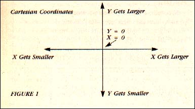
The drawing screen uses standard Cartesian coordinates, which are much better suited to 3-D graphics than the Atari's coordinate system. (see Figure 1.)
To select a control point location, use the joystick to move your cursor to the chosen position and press the joystick button. When designing the profile, it may help you to think of the Y value as the depth of the object you are creating and the X value as the radius.
 After you have selected all your control points, the program starts calculating the wire frame data. This may take a while, depending on the number of control points and sides you selected. For a graph with 10 control points and 10 sides, the program must calculate 100 data points, using several loops and a lot of SIN() and COS().
After the data has been calculated. the program will draw the image on the screen. At this point two things can happen: 1. Drawing the object will be completed and you'll have your first Easy 3-D Wire Frames graphic. 2. You will see the message "Fitting To Screen." This means the object you created is too big to be displayed completely onscreen, so the program is scaling it down for you.
After displaying the graph, another prompt appears in the text window: View, New, Print, Save, Quit. Type the first letter of the function you want and press [RETURN].
View: This option lets you edit the values that you entered earlier--Magnification, MX, MY, MZ, Yaw, Roll and Pitch. Like the main menu, it tells you what the current value is. Press [RETURN] to keep this value, or type in a new one.
New: This re-starts the program.
Print: This option presents you with yet another menu. You can select "Data," which prints a table of all the values used, to create the wire-frame. If you have an Atari 1020 Plotter attached, you can select "Graph." This gives you a very nice printout of the wire frame drawing. I purposely made the Graph routine the last section in the program, so that those without a 1020 Plotter can substitute their favorite printing graph routine here.
Save: This stores your wire frame on disk. You can save it as a data file, a Micro-Painter compatible picture file, or both. If you want to be able to reload your wire frame, be sure to save it as a data file.
When you choose the Save function, you'll first be prompted for a filename for the data file. Remember to include the drive number as part of the filename (example, D1:SPHERE.3D). If you don't want to save the wire frame as a data file, just press [RETURN].
Next you'll be prompted for a filename for the picture file. Type a filename, as before. Again, if you don't want to save the wire frame as a picture file, just press [RETURN].
Easy 3-D Wire Frames saves images as 62-sector Micro-Painter files. These can't be reloaded into Easy 3-D Wire Frames, but may be used with many painting and animation programs. Rapict Graphics Converter (Antic, November 1985) enables you to use these pictures with even more kinds of graphics software.
Quit: Quits.
Robert Geddings of Eugene, Oregon published PolyMove in the August 1987 Antic.
Listing1:SPIN.BAS Download
Listing2:COCKTAIL.DAT Download
Listing3:COCKTAIL.MIC Download