Customizing the Atari
Operating System
Device Handlers:
Part 1
By Bob Martin & Martin Mercorelli
This article, the first of a two-part series for experienced BASIC programmers, explalns how the Atari operating system handles the various devices attached to your computer and gives you a step-by-step approach to adding a new device handler or modifying an existing one. The BASIC programs work with any Atari 8-bit computer, disk or cassette.
The ability to change your computer's operating system is a very powerful technique. Atari 8-bit owners are in for a treat, because there are several ways to customize your system through software. To illustrate, two programs are included with this article. The first creates a device handler that does nothing. (Believe it or not, that can be useful.) The second modifies the printer handler to print non-printing characters.
The printer handler was written for the Epson RX-80 and the C.Itoh Prowriter, but it should work with any printer capable of dot-graphics printing. Each program illustrates a different aspect of creating device handlers.
What good is adding a device handler to the operating system instead of having your program perform the same function? To answer this, let's look at how the operating system interacts with the outside world.
CIO ROUTINE
Among the Atari operating system's best features is the way it handles input and output (I/O). All I/O operations are generally performed in the same way, regardless of which peripheral device is accessed---disk drive, keyboard, screen editor or printer. We can simplify I/O because it's normally handled through the Central Input/Output routine (CIO).
In BASIC, I/O is done so naturally that you hardly notice the complexity of what is actually happening. One example is the use of CIO to send data to the printer:
First, open the device through a CIO control block with the command OPEN #3,8,O,"P:". This does three things: 1) it tells the operating system to OPEN CIO control block #3 (IOCB3) for I/O and to prepare for I/O to the printer; 2) the 8 tells the operating system that data will flow from the computer to the printer; and 3) the "P:" tells the computer to send data to the printer. Therefore the OPEN command is for initialization.
Summing up, a device handler simply tells the computer how to talk to a device. The computer needs to know the direction of data flow, which path (or channel) it will use, where to find data, where to put it and how much of it to grab.
DEVICE HANDLERS
If CIO is the computer's I/O interfnce to the user, then the device handlers are the computer's interface to peripheral devices.
For example, how does the computer send data to the printer? Since the printer isn't a disk drive or keyboard, your Atari obviously needs a special routine, which is part of the device handler.
Each device handler has six routines: OPEN, CLOSE, GET, PUT, STATUS, and SPECIAL (See Figure 1). In BASIC these machine language routines are controlled through I/O commands. For example, when your program issues the command OPEN #3,8,0,"P:" it is actually using the OPEN part of the printer handler.
Every handler contains six machine language routines and a table containing the address of each routine minus one.
Why the minus one? CIO accesses a function by pushing its address onto the stack, then executing an RTS (ReTurn from Subroutine). The RTS instruction directs the program to the address on the stack plus one. To arrive at the correct address, we must compensate by subtracting one from our target address.
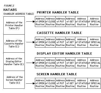
HATABS
CIO finds the address of the appropriate handler table in the Handler Address Table, HATABS. This table is a 38-byte block of memory occupying locations 734--831 ($031A--$033F).
Each device handler has its own three-byte entry in the Handler Address Table. The first byte is an ASCII character representing the name of the device (K for keyboard, D for disk drive, etc.). The next two bytes hold the address of that device's handler table.
When you issue an OPEN #3,8,O,"P:" command, for example, CIO looks through HATABS for a "P:". Then it uses the next two bytes to find the address of the printer's handler table. Once found, CIO searches the printer's handler table for the address of the printer handler's OPEN routine. Finally, CIO executes the printer handler's OPEN routine (See Figure 2).
Again, CIO finds the handler in two steps:
- 1) Get the address of the appropriate handler table from HATABS.
- 2) Get the address of the handler routines from the handler table.
WRITING YOUR OWN HANDLER
Now that we know how CIO locates the handler table, here's how to make your own handler:
1) Write the program for the handler. (The handler must have the functions listed in Figure 1.)
2) Set up a Handler Table with the address of each function (minus one) in the order given in Figure 1. The special function is a jump instruction beginning with a decimal 76, followed by the two-byte address of the special routine.
3) Make an entry in the Handler Address Table for the device.
That's all. Now let's focus on the two examples and how they implement these steps.
NULL HANDLER
Type in Listing 1,NULLHAND.BAS, check it with TYPO II and SAVE a copy before you RUN it. When RUN, NULLHAND.BAS installs the Null Handler, N:, on Page Six. Once installed, you can test the handler by typing:
LIST "N:"
This command LISTs the program to the N: device. If your Atari responds with a "READY" prompt, the handler is properly installed. If you get an error message, however, something went wrong. Check NULLHAND.BAS for typing errors, and try again.
One use of the null handler is to check a disk for a scrambled file (Error 164). One way to check is to use DOS to copy the file to the screen. This, however, is quite time- consuming. Instead, copy the file to the N: device. The Null Handler will do the job in a jiffy.
To copy a file to the Null Handler, select choice C from the DOS menu and type: D:filename, N:
If the file is read completely without error, then it's intact. All the files on a disk can be checked by typing "D: *.*,N''
| Figure 1 | ||||||||
|
PROGRAM TAKE-APART
Listing 2, NULLHAND.M65, is the MAC/6S assembly language source code for NULLHAND.BAS. You do not need to type it to use the N handler.
Lines 540-590 contain the N: handler's routines (see step 1, above). Since the N: handler does nothing, all six functions can be handled by the same "do-nothing" routine. This routine does nothing but end with an RTS instruction and return the appropriate error codes to CIO. All handler routines must do this.
Ending in an RTS means that CIO pushes the return address on the stack before jumping to the handler. This feature is useful if you're modifying an existing handler because it gives you two entry points.
Error codes are handled the same way. When CIO jumps to the handler, the Y register contains error code 146--"Function not implemented in handler." If the Y register isn't changed, CIO will print "ERROR 146" and return control to you. Since the handler does nothing, the only error message to return is 1, "No error has occurred." It should be in both the accumulator and the Y register. So putting a 1 into the A and Y registers is all this handler does before executing the RTS.
Lines 440-520 build a Handler Talble for the N: handler (see step 2, above). Since all the functions are the same, there are five NULL-1 values followed by one JMP NULL. The Handler Table is always that easy to write--although the addresses usually aren't all the same. Just remember to subtract 1 from each of the first five functions.
Lines 220-420 insert the N: device and the address of the N: handler table into the Handler Address Table (See step 3). This is the most complicated part of the program. Lines 220- 310 look for a blank spot in HATABS. Lines 350-420 place the ASCII value for N into HATABS, followed by the two-byte address of the N: handler table (low byte, high byte).
Since the letters indicating the devices are separated by a two-byte address, the routine that searches for a blank spot checks every third byte in HATABS.
Finally, we place the program's initialization address, INSERT, into INITAD (location 738, $02E2). This forces the program to start as soon as t is loaded into memory. Ending the initialization routine with an RTS returns control to DOS.
USING PRINT HANDLER
The modified printer handler makes it easier to get a hard copy of a file or BASIC program containing non-printing characters (such as the "clear screen" character). Normally, non-printing characters aren't printed. But a special problem arises when the printer recognizes a character as a control character. Control characters are acted upon, not printed. And at the very least, they produce a messy printout. But with the modified printer handler, a neat printout is easily produced.
Type in listing 3, PRHAND.BAS, checking it with TYPO II, and SAVE a copy before you RUN it. When RUN, the program will ask you what type of printer you own. Type [1] if you own an Epson printer, [2] if you own a C.Itoh printer, or [3] for other types of printers. Next, press [RETURN] and the program will create a file called EPSON.EXE (or CITOH.EXE for C.Itoh owners). This is the program which creates and installs the new printer handler. Antic Disk Subscribers will find both versions on the monthly disk.
Copy the appropriate .EXE file to a DOS 2.0 of DOS 2.5 disk. Make sure this disk has a DOS.SYS file. Next, rename the .EXE file to AUTORUN.SYS. This disk will automatically install the new printer handler each time you boot your system with it.
Once installed, 1791,255 to activate the handler. POKE a zero into 1791 to return to normal printer operation. Your Atari will use the modified printer handler until you turn off the computer or press [RESET].
Listing 4, PRHAND.MGS, is the MAC/65 source code for the printer handler. You do not need to type it.
TAKE APART
The only difference in our printer-handler is the PUT BYTE routine, lines 1030--2570.
Line 290 jumps to the old PUT BYTE routine, and the rest of it just checks for non-printing characters and supplies graphics data.
For the PUT BYTE routine, the byte to be sent is in the accumulator when CIO jumps to the handler. This routine first checks location 1791 ($06FF) to see if the modification is enabled. If so, it then checks to see if the byte to be sent is a non-printing character. For a non-printing character, the control code for eight dot-graphics bytes is sent, followed by the dot-graphics data.
Most printers plot dot graphics the same way. First, the printer is sent a control code enabling dot-graphics mode. On Epsons and compatible printers, the code is 27, 76 ([ESC]-[L]). Then comes the number of bytes the printer should expect. On Epsons and compatibles, a two-byte integer (low byte, high byte) is sent. The complete command for eight-dot graphics mode bytes is 27,76,8,0. On the C.Itoh and compatibles, it's 27,83,48,48,56 (or [ESC]-[S]-[0]-[0]-[8]). Then the eight bytes of graphics data are sent to the printer.
To use character data from the Atari internal character set, we must make it acceptable to the printer. Although your Atari and your printer can define a character in eight bytes, they arrange these bytes differently.
The Atari's character set is organized in horizontal slices starting at the top, and the printer needs vertical slices starring to the left of the character.
To change a screen character data for the printer, each byte for the screen must be sliced one bit at a time, re-formed into eight new bytes and sent to the printer. In other words, bit zero becomes byte one for the printer, bit one becomes byte two, etc.
Lines 210-240 contain the handler table. This table is even simpler than the last one. The new handler table is left blank so that the old table can be copied to it. Notice that the fourth two-byte address (corresponding to the location of the PUT BYTE routine) has a label, making it easy to store the location of the PUT BYTE routine in the new handler table.
Lines 340-800 contain the initialization routine. Lines 340-430 search for the P: handler entry in HATABS. Then lines 460-620 copy the following address to a zero page location and replace the P: handler table address with the address of the new P: handler. The old PUT BYTE address is copied to the jump instruction (line 290) after adding 1. And the new PUT BYTE routine address (minus 1) is placed in the new handler table. Finally, the address of INSERT is stored at $02E2.
NEXT MONTH
Both handlers operate without communicating with the user. The ability to let the user select options is often important for a handler. In Part 2 of the series we'll add I/O to the screen and add everything necessary for a complete handler.
Remember that when writing a device programmer you only need to worry about half of the I/O conversation---CIO does the rest.