 Mapping the Atari Exclusive! (Part 2)
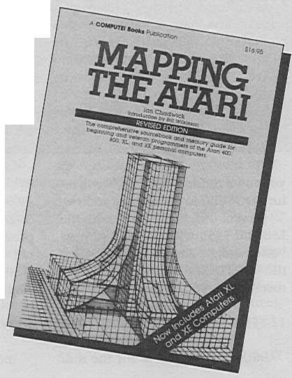
Classic 8-bit reference book returns.
By Ian Chadwick
Antic continues the exclusive serialization of key excerpts from the revised second edition of Ian Chadwick's "Mapping the Atari." Virtually impossible to obtain today, this book has been one of the key reference sources for Atari 8-bit programmers since 1983.
The August 1989 issue of Antic explained many of the uses for a comprehensive Atari memory location guide which we now begin presenting this month.
Locations zero to 255 ($0 to $FF) are called "page zero" and have special importance for assembly language programmers since these locations are accessed faster and easier by the machine.
Locations zero to 127 ($0 to $7F) are reserved as the OS page zero, while 128 to 255 ($80 to $FF) are the BASIC and the user zero page RAM.
Locations zero to 1792 ($0 to $700) are all used as the OS and (if the cartridge is present) 8K BASIC RAM (except page six). Locations zero to 8191 ($0 to $1FFF) are the minimum required for operation (8K).
Locations two through seven are not cleared on any start operation.
| DECIMAL | HEX | LABEL |
| 0,1 | 0,1 | LINZBS |
| LINBUG RAM, replaced by the monitor RAM. It seems to be used to store the VBLANK timer value. One user application I've seen for location zero is in a metronome program in De Re Atari. Also used in cross-assembling the Atari OS. | ||
| 2,3 | 2,3 | CASINI |
| Cassette initialization vector: JSR through here if the cassette boot was successful. This address is extracted from the first six bytes of a cassette boot file. | ||
| 4,5 | 4,5 | RAMLO |
| RAM pointer for the memory test used on powerup. Also used to store the disk boot address -- normally 1798 (S706)-for the boot continuation routine. | ||
| 6 | 6 | TRAMSZ |
| Temporary Register for RAM size; used during powerup sequence to test RAM availability. This value is then moved to RAMTOP, location 106 ($6A). Reads One when the BASIC or the A (left) cartridge is plugged in. | ||
| 7 | 7 | TSTDAT |
| RAM test data register. Reads one when the B or the right cartridge is inserted. | ||
RAMLO, TRAMSZ and TSTDAT are all used in testing the RAM size on powerup. On DOS boot, RAMLO and TRAMSZ also act as temporary storage for the boot continuation address. TRAMSZ and TSTDAT are used later to flag whether or not the A (left) and/or B (right) cartridges, respectively, are plugged in (non-zero equals cartridge plugged in) and whether the disk is to be booted.
Locations eight through 15 (S8-$F) are cleared on coldstart only.
| 8 | 8 | WARMST |
| Warmstart flag. If the location reads zero, then it is in the middle of powerup; 255 is the normal RESET status. Warmstart is similar to pressing RESET, so should not wipe out memory, variables, or programs. | ||
| 9 | 9 | BOOT? |
| Boot flag success indicator. A value of 255 in this location will cause the system to lockup if RESET is pressed. If BOOT? reads one, then the disk boot was successful; if it reads two, then the cassette boot was successful. | ||
| 10,11 | A,B | DOSVEC |
| Start vector for disk (or non-cartridge software. This is the address BASIC jumps to when you call up DOS. Can be set by user to point to your own routine, hot RESET will return DOSVEC to the original address. To prevent this, POKE 5446 with the LSB and 5450 with the MSB of your vector address and re-save DOS using the WRITE DOS FILES option in the menu. | ||
| 12,13 | C,D | DOSINI |
| Initialization address for the disk boot. Also used to store the cassette-boot RUN address, which is then moved to CASINI (2.3). When you powerup without either the disk or an autoboot cassette tape, DOSINI will read zero in both locations. | ||
| 14,15 | E,F | APPMHI |
| Applications memory high limit and pointer to the end of your BASIC program, used by both the OS and BASIC It contains the lowest address you can use to set up a screen and Display List (which is also the highest address usable for programs and data below which the display RAM may not be placed). | ||
| 16 | 10 | POKMSK |
| POKEY interrupts: the IRQ service uses and alters this location. Shadow for 53774 ($D20E). POKE with 112 ($70; also POKE this same value into 53774) to disable the BREAK key. If the following bits are set (to one), then these interrupts arc enabled (bit decimal values are in parentheses): | ||
| BIT | DECIMAL | FUNCTION |
| 7 | 128 | The BREAK key is enabled. |
| 6 | 64 | The "other key" interrupt is enabled. |
| 5 | 32 | The serial input data ready interrupt is enabled. |
| 4 | 16 | The serial output dam required interrupt is enabled. |
| 3 | 8 | The serial out transmission finished interrupt is enabled. |
| 2 | 4 | The POKEY timer four interrupt is enabled (only in the "B" or later versions of the OS ROMs). |
| 1 | 2 | The POKEY timer two interrupt is enabled. |
| 0 | 1 | The POKEY timer one interrupt is enabled |
| 17 | 11 | BRKKEY |
| Zero means the BREAK key is pressed; any other number means it's not. A BREAK during 1/O returns 128 ($80). Monitored by both keyboard, display, cassette and screen handlers. | ||
| 18,19,20 | 12,13,14 | RTCLOK |
| Internal realtime clock. Location 20 increments every stage one VBLANK interrupt (1/60 second = one jiffy) until it reaches 255 ($FF); then location 19 is incremented by oncand 20 a reset to zero (every 4.27 seconds). When location 19 reaches 255, it and 20 are reset to zero and location 18 is incremented by one (every 18.2 minutes or 65536 TV frames). | ||
| 21,22 | 15,16 | BUFADR |
| Indirect buffer address register (page zero). Temporary pointer to the current disk buffer. | ||
| 23 | 17 | ICCOMT |
| Command for CIO vector. Stores the CIO command; used to find the offset in the command table for the correct vector to the handler routine. | ||
| 24,25 | 18,19 | DSKFMS |
| Disk file manager pointer. Called JMPTBL by DOS; used as vector to FMS. | ||
| 26,27 | 1A,1B | DSKUTL |
| The disk utilities pointer. Called BUFADR by DOS, it points to the area saved for a buffer for the utilities package (data buffer; DBUF) or for the program area (MEMLO; 743, 744; $2E7, $2E8). | ||
| 28 | 1C | PTIMOT |
| Printer timeout, called every printer status request. Initialized to 30, which represents 32 seconds (the value is 64 seconds per 60 increments in this register); typical timeout for the Atari 825 printer is five seconds. The value is set by your printer handler software. It is updated after each printer status request operation. It gets the specific timeout status from location 748 ($2EC), which is loaded there by SIO. | ||
| 29 | 1D | PBPNT |
| Print buffer pointer; points to the current position (byte) in the print buffer. Ranges from zero to the value in location 30. | ||
| 30 | 1E | PBUFSZ |
| Print buffer size of printer record for current mode. Normal buffer size and line size equals 40 bytes; double-width print equals 20 bytes (most printers use their own control codes for expanded print); sideways printing equals 29 bytes (Atari 820 printer only). Printer status request equals four. PBUFSZ is initialized to 40. The printer handler checks to see if the same value is in PBPNT and, if so, sends the contents of the buffer to the printer. | ||
| 31 | 1F | PTEMP |
| Temporary register used by the printer handler for the value of the character being output to the printer. | ||
THE ZIOCB
Locations 32 to 47 ($20 to $2F) are the ZIOCB: Page zero Input-Output control Block. They use the same structure as the IOCB's at locations 832 to 959 ($340 to $3BF). The ZIOCB is used to communicate I/O control data between CIO and the device handlers. When a CIO operation is initiated, the information stored in the IOCB channel is moved here for use by the CIO routines. When the operation is finished, the updated information is returned to the user area.
| 32 | 20 | ICHIDZ |
| Handler index number. Set by the OS as an index to the device name table for the currently open file. If no file is open on this IOCB (IOCB free), then this register is set to 255 ($FF). | ||
| 33 | 21 | ICDNOZ |
| Device number or drive number. Called MAXDEV by DOS to indicate the maximum number of devices. Initialized to one. | ||
| 34 | 22 | ICCOMZ |
| Command code byte set by the user to define how the rest of the IOCB is formatted, and what I/O action is to be performed. | ||
| 35 | 23 | ICSTAZ |
| Status of the last IOCB action returned by the device, set by the OS. May or may not be the same status returned by the STATUS command. | ||
| 36,37 | 24,25 | ICBALZ/HZ |
| Buffer address for data transfer or the address of the file name for commands such as OPEN, STATUS, etc. | ||
| 38,39 | 26,27 | ICPTLZ/HZ |
| Put byte routine address set by the OS. It is the address minus one byte of the device's "put one byte" routine It points to CIO's "IOCB not OPEN" on a CLOSE statement. | ||
| 40,41 | 28,29 | ICBLLZ/HZ |
| Buffer length byte count used for PUT and GET operations; decreased by one for each byte transferred. | ||
| 42 | 2A | ICAXIZ |
| Auxiliary information first byte used in OPEN to specify the type of file access needed. | ||
| 43 | 2B | ICAX2Z |
| CIO working variables, also used by some serial port functions. Auxiliary information second byte. | ||
| 44,45 | 2C,2D | ICAX3Z/4Z |
| Used by BASIC NOTE and POINT commands for the transfer of disk sector numbers. These next four bytes to location 47 are also labelled as: ICSPRZ and are defined as spare bytes for local CIO use. | ||
| 46 | 2E | ICAX5Z |
| The byte being accessed within the sector noted in locations 44 and 45. It is also used for the IOCB Number multiplied by 16. Each IOCB block is 16 bytes long. Other sources indicate that the 6502 X register also contains this information. | ||
| 47 | 2F | ICAX6Z |
| Spare byte. Also labeled CIOCHR, it is the temporary storage for the character byte in the current PUT operation. | ||
| 48 | 30 | STATUS |
| Internal status storage. The SIO routines in ROM use this byte to store the status of the current SIO operation. | ||
| 49 | 31 | CHKSUM |
| Data frame checksum used by SIO: single byte sum with carry to the least significant bit. Checksum is the value of the number of bytes transmitted (255; $FF). When the number of transmitted bytes equals the checksum, a checksum sent flag is set at 1ocation 59 ($3B). Uses locations 53773 ($D20D) and 56 ($38) for comparison of values (bytes transmitted). | ||
| 50,51 | 32,33 | BUFRL/HI |
| Pointer to the data buffer, the contents of which are transmitted during an I/O operation, used by SIO and the Device Control Block (DCB); points to the byte to send or receive. Bytes are transferred to the eight-bit parallel serial output holding register or from the input holding register at 53773 ($D20D). | ||
| 52,53 | 34,35 | BFENLO/HI |
| Next byte past the end of the SIO and DCB data buffer described above | ||
| 54 | 36 | CRETRY |
| Number of command frame retries. Default is 13 ($0D). This is the number of times a device will attempt to carry out a command such as read a sector or format a disk. | ||
| 55 | 37 | DRETRY |
| Number of device retries. The default is one. | ||
| 56 | 38 | BUFRFL |
| Data buffer full flag (255; $FF equals full). | ||
| 57 | 39 | RECVDN |
| Receive done flag (255: $FF equals done). | ||
| 58 | 3A | XMTDON |
| Transmission done flag (255; $FF equals done). | ||
| 59 | 3B | CHKSNT |
| Checksum sent flag (255; $FF equals sent). | ||
| 60 | 3C | NOCKSM |
| Flag for "no checksum follows data." Not zero means no checksum follows; zero equals checksum follows transmission data. | ||
| 61 | 3D | BPTR |
| Cassette buffer pointer: record data index into the portion of data being read or written. Ranges from zero to the current value at location 650 ($28A). | ||
| 62 | 3E | FTYPE |
| Inter record gap type between cassette records, copied from location 43 ($2B; ICAX2Z) in the ZIOCB, stored there from DAUX2 (779; $30B) by the user. | ||
| 63 | 3F | FEOF |
| Cassette end of file flag. If the value is zero, an end of file (EOF) has not been reached. Any other number means it has been detected. | ||
| 64 | 40 | FREQ |
| Beep count retain register. Counts the number of beeps required by the cassette handler during the OPEN command for play or record operations; one beep for play, two for record. | ||
| 65 | 41 | SOUNDR |
| Noisy I/O flag used by SIO to signal the beeping heard during disk and cassette 1/O. POKE here with zero for blessed silence during these operations. Other numbers return the beep. Initialized to three. | ||
| 66 | 42 | CRITIC |
| Critical I/O region flag; defines the current operation as a time critical section when the value here is non-zero. Checked at the NMI process after the stage one VBLANK has been processed. POKEing any number other than zero here will disable the repeat action of the keys and change the sound of the CTRL-2 buzzer. Zero is normal; setting CRITIC to a non-zero value suspends a number of OS processes including system software timer counting (timers two, three, four and five). |
||
| 67-73 | 43-49 | FMZSPG |
| Disk file manager system (FMS) page zero registers (seven bytes). | ||
| 67,68 | 43,44 | ZBUFP |
| Page zero buffer pointer to the user filename for disk I/O. | ||
| 69,70 | 45,46 | ZDRVA |
| Page zero drive pointer. Copied to here from DBUFAL and DBUFAH; 4905 and 4913 ($1329, $1331). Also used in FMS "free sector," setup and "get sector" routines | ||
| 71,72 | 47,48 | ZSBA |
| Zero page sector buffer pointer. | ||
| 73 | 49 | ERRNO |
| Disk 1/O error number. Initialized to 159 ($9F) by FMS. | ||
| 74 | 4A | CKEY |
| Cassette boot request flag on coldstart. Checks to see if the START key is pressed and, if so, CKEY is set. | ||
| 75 | 4B | CASSBT |
| Cassette boot flag, The Atari attempts both a disk and a cassette boot simultaneously. Zero here means no cassette boot was successful. | ||
| 76 | 4C | DSTAT |
| Display status and keyboard register used by the display handler. Also used to indicate memory is too small for the screen mode, cursor out of range error, and the BREAK abort status. | ||
| 77 | 4D | ATRACT |
| Attract mode timer and flag. Attract mode rotates colors on your screen at low luminance levels when the computer is on but no keyboard input is read for a long time (seven to nine minutes). This helps to save your TV screen from "burn-out" damage suffered from being left on and not used. It is set to zero by IRQ whenever a key is pressed, otherwise incremented every four seconds by VBLANK (see locations 18-20; $12-$14). When the value in ATRACT reaches 127 ($7F), it is then set to 254 ($FE) until attract mode is terminated. This sets the flag to reduce the luminance and rotate the colors when the Atari is sitting idle. | ||
| 78 | 4E | DRKMSK |
| Dark attract mask; set to 254 ($FE) for normal brightness when the attract mode is inactive (see location 77). Set to 246 ($F6) when the attract mode is active to guarantee screen color luminance will not exceed 50+. Initialized to 254 ($FE). | ||
| 79 | 4F | COLRSH |
| Color shift mask; attract color shifter; the color registers are EORd with locations 78 and 79 at the stage two VBLANK (see locations 18-20; $12-$14). When set to zero and location 78 equals 246, color luminance is reduced 50%. COLORSH contains the current value of location 19, therefore is given a new color value ever 4.27 seconds. | ||
Bytes 80 to 122 ($50 to $7A) are used by the screen editor and display handler.
| 80 | 50 | TEMP |
| Temporary register used by the display handler in moving data to and from screen. Also called TMPCHR. | ||
| 81 | 51 | HOLD1 |
| Same as location 80. It is used also to hold the number of Display List entries. | ||
| 82 | 52 | LMARGN |
| Column of the left margin of text (GR.O or text window only). Zero is the value for the left edge of the screen; LMARGN is initialized to two. You can POKE the margin locations to set them to your specific program needs, such as POKE 82,10 to make the left margin start ten locations from the edge of the screen. | ||
| 83 | 53 | RMARGN |
| Right margin of the text screen, initialized to 39 ($27). | ||
| 84 | 54 | ROWCRS |
| Current graphics or text screen cursor row, value ranging from zero to 191 ($BF) depending on the current GRAPHICS mode (maximum number of rows, minus one). This location, together with location 85 below, defines the cursor location for the next element to be read/written to the screen. Rows run horizontally, left to right across the TV screen. Row zero is the topmost line; row 192 is the maximum value for the bottom-most line. | ||
| 85,86 | 55,56 | COLCRS |
| Current graphics or text mode cursor column; values range from zero to 319 (high byte, for screen mode eight) depending on current GRAPHICS mode (maximum number of columns minus one). Location 86 will always be zero in modes zero through seven. Home position is 0,0 (upper left-hand comer). Columns run vertically from the top to the bottom down the TV screen, the leftmost column being number zero, the rightmost column the maximum value in that mode. The cursor has a complete top to bottom, left to right wraparound on the screen. | ||
| 87 | 57 | DINDEX |
| Display mode/current screen mode. Labelled CRMODE by (*M). DINDEX contains the number obtained front the low order four bits of most recent open AUX1 byte. It can be used to fool the OS into thinking you are in a different GRAPHICS mode by POKEing DINDEX with a number from zero to 11. POKE with seven after you have entered GRAPHICS mode eight, and it will give you a split screen with mode seven on top and mode eight below. However, in order to use both halves of the screen, you will have to modify location 89 (below) to point to the area of the screen you wish to DRAW in. | ||
| 88,89 | 58,59 | SAVMSC |
| The lowest address of the screen memory, corresponding to the upper left corner of the screen (where the value at this address will be displayed). The upper left corner of the text window is stored at locations 660, 661 ($294, $295). | ||
| 90 | 5A | OLDROW |
| Previous graphics cursor row. Updated from location 84 ($54) before every operation. Used to determine the starting row for the DRAWTO and XIO 18 (FILL command). | ||
| 91,92 | 5B,5C | OLDCOL |
| Previous graphics cursor column. Updated from locations 85 and 86 ($55, $56) before every operation. These locations are used by the DRAWTO and XIO 18 (FILL) commands to determine the starting column of the DRAW or FILL. | ||
| 93 | 5D | OLDCHR |
| Retains the value of the character under the cursor, used to restore that character when the cursor moves. | ||
| 94,95 | 5E,5F | OLDADR |
| Retains the memory location of the current cursor location. Used with location 93 (above) to restore the character under the cursor when the cursor moves. | ||
| 96 | 60 | NEWROW |
| Point (row) to which DRAWTO and X10 18 (FILL) will go. | ||
| 97,98 | 61,62 | NEWCOL |
| Point (column) to which DRAWTO and XIO 18 (FILL) will go. NEWROW and NEWCOL are initialized to the values in ROWCRS and COLCRS (84 to 86; $54 to $56) above, which represent the destination end point of the DRAW and FILL functions. This is done so that ROWCRS and COLCRS can be altered during these routines. | ||
| 99 | 63 | LOGCOL |
| Position of the cursor at the column in a logical line A logical line can contain up to three physical lines, so LOGCOL can range between zero and 119. Used by the display handler. | ||
| 100,101 | 64,65 | ADRESS |
| Temporary storage used by the display handler for the Display List address, line buffer (583 to 622; $247 to $26E), new MEMTOP value after DL entry, row column address, DMASK value, data to the right of cursor, scroll, delete, the clear screen routine and for the screen address memory (locations 88, 89; $58, $59). | ||
| 102,103 | 66,67 | MLTTMP |
| Also called OPNTMP and TOADR; first byte used in OPEN as temporary storage. Also used by the display handler as temporary storage. | ||
| 104,105 | 68,69 | SAVADR |
| Also called FRMADR. Temporary storage, used with ADRESS above for the data under the cursor and in moving line data on the screen. | ||
| 106 | 6A | RAMTOP |
| RAM size, defined by powerup as passed from TRAMSZ (location 6), given in the total number of available pages (one page equals 256 bytes, so PEEK(106)*256 will tell you where the Atari thinks the last usable address-byte-of RAM is). MEMTOP (741,742; $2E5,$2E6) may not extend below this value. In a 48K Atari, RAMTOP is initialized to 160 ($A0), which points to location 40960 ($A000). The user's highest address will be one byte less than this value. | ||
| 107 | 6B | BUFCNT |
| Buffer count: the screen editor current logical line size counter. | ||
| 108,109 | 6C,6D | BUFSTR |
| Editor low byte (AM). Display editor GETCH routine pointer (location 62867 for entry; $F593). Temporary storage; returns the character pointed to by BUFCNT above. | ||
| 110 | 6E | BITMSK |
| Bit mask used in bit mapping routines by the OS display handler at locations 64235 to 64305 ($FAEB to $FB31). Also used as a display handler temporary storage register. | ||
| 111 | 6F | SHFAMT |
| Pixel justification: the amount to shift the right Justified pixel data on output or the amount to shift the input data to right justify it. Prior to the justification process, this value is always the same as that in 672 ($2A0) | ||
Continued next issue
Copyright 1983 and 1985, COMPUTE! Publications, Inc.
MAPPING THE ATARI
$16.95, COMPUTE! Books, PO. Box
5406, Greensboro, North Carolina
27403, (919) 275-9809.
Ian Chadwick is a Toronto-based freelance Writer.